Mazda CX-5 Service & Repair Manual: Map Light Bulb Removal/Installation
Front Map Light
1. Disconnect the negative battery cable..
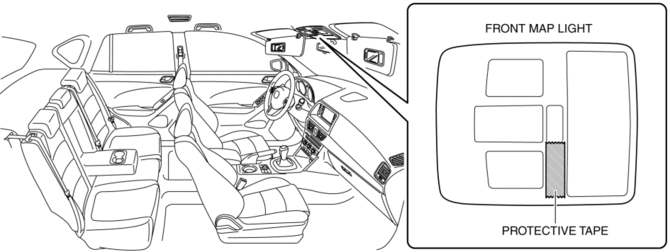
2. To prevent scratches or damage, affix protective tape to the position shown in the figure.
CAUTION:
-
If a flathead screwdriver is inserted into the gap between the front map light and lens, the front map light could interfere with the flathead screwdriver resulting in damage to the front map light. When removing the lens from the front map light, perform the procedure after affixing protective tape to the front map light.
3. Press the lens to secure a sufficient space for inserting a flathead screwdriver.
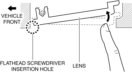
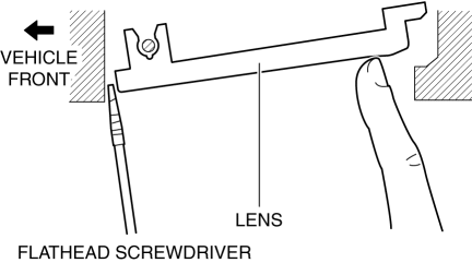
4. Insert a tape-wrapped flathead screwdriver into the gap between the lens and front map light shown in the figure.
5. Move the flathead screwdriver in the direction of the arrow (1) shown in the figure, pull out the lens from the front map light, and detach the front map light pin and lens.
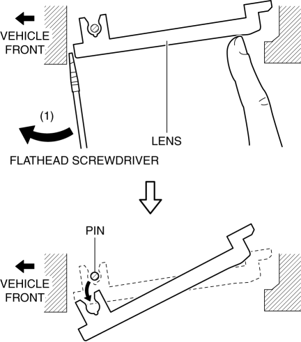
6. Remove the lens.
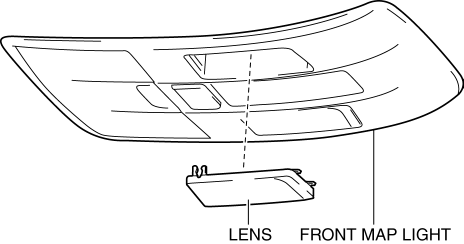
7. Press the front map light spring in the direction of the arrow (2) shown in the figure and detach the front map light spring and front map light bulb.
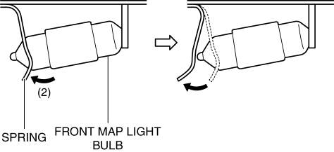
8. Remove the front map light bulb.
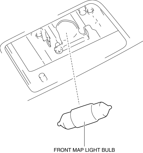
9. Install in the reverse order of removal.
Rear Map Light
1. Disconnect the negative battery cable..
2. To prevent scratches or damage, affix protective tape to the position shown in the figure.
CAUTION:
-
If a flathead screwdriver is inserted into the gap between the rear map light and lens, the rear map light could interfere with the flathead screwdriver resulting in damage to the rear map light. When removing the lens from the rear map light, perform the procedure after affixing protective tape to the rear map light.
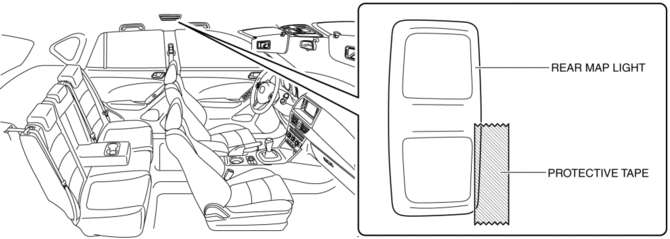
3. Press the lens to secure a sufficient space for inserting a flathead screwdriver.
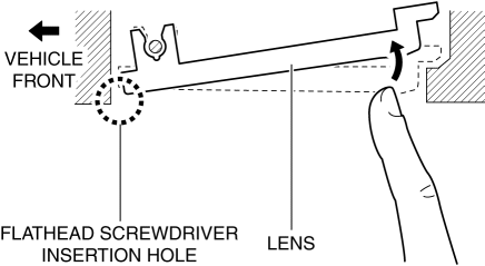
4. Insert a tape-wrapped flathead screwdriver into the gap between the lens and rear map light shown in the figure.
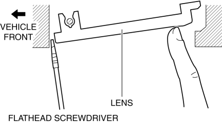
5. Move the flathead screwdriver in the direction of the arrow (1) shown in the figure, pull out the lens from the rear map light, and detach the rear map light pin and lens.
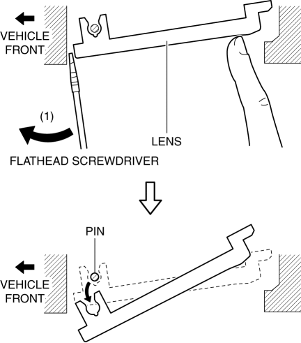
6. Remove the lens.
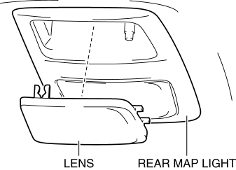
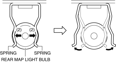
7. Move the rear map light spring in the direction of the arrow (2) shown in the figure and detach the rear map light spring and rear map light bulb.
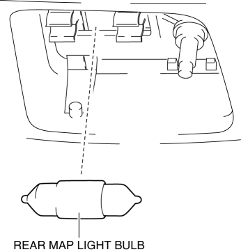
8. Remove the rear map light bulb.
9. Install in the reverse order of removal.
 Interior Lighting System
Outline
A room light control system has been adopted in which illumination time and
illumination level of the interior lights change.
The rear body control module (RBCM) performs roo ...
 Map Light Inspection
Front Map Light
1. Disconnect the negative battery cable..
2. Remove the front map light..
3. Verify that the continuity between the front map light terminals is as indicated
in the table.
...
Other materials:
Sas Control Module [Standard Deployment Control System]
Purpose
The SAS control module controls the air bag system operation.
Function
During a frontal collision, the SAS control module controls the following
air bag module operation (deployment).
Driver-side air bag module
Passenger-side air bag module
...
Rear Stabilizer Removal/Installation [Awd]
WARNING:
Verify that the rear crossmember is securely supported by a jack. If the
rear crossmember falls off, it can cause serious injury or death, and damage
to the vehicle.
CAUTION:
Performing the following procedures without first removing the rear ABS wheel-speed
s ...
Rear Seat Center Armrest Removal/Installation
1. Operate the push knob (RH) and lower the rear seat back (RH).
2. Remove screw A.
3. Remove the rear seat center armrest hinge cover (RH) in the direction of the
arrow (1) shown in the figure while setting hook A aside.
4. Remove bolt B.
5. Remove the rear seat center armrest in ...
