Mazda CX-5 Service & Repair Manual: Lap Pre Tensioner Seat Belt [Two Step Deployment Control System]
Purpose
-
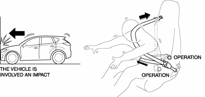
The lap pre-tensioner seat belts retract and tighten the seat belt webbing to protect the front passengers during a collision.
Function
-
The lap pre-tensioner seat belts operate (deploy) based on the operation signal from the SAS control module to instantly retract and tighten the belt webbing, restraining the driver.
-
The lap pre-tensioner seat belts operate in conjunction with the pre-tensioner seat belts.
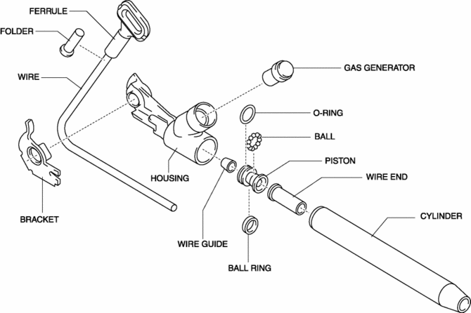
Construction
-
The lap pre-tensioner seat belts are installed to the anchors of the front seat belts.
-
The lap pre-tensioner seat belts consist of the following parts shown in the figure:
Operation
Lap pre-tensioner activation
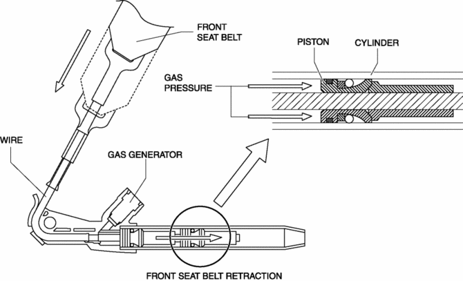
1. The gas generator emits a spark when a signal is received from the SAS control module, causing gas to form.
2. The gas pressure pushes the piston inside the tube, pulling the lead wire.
3. As the lead wire is pulled, the part of the seat belt attached to the wire is also pulled.
4. The slack in the belt is tightened by the front seat belt being pulled by the lap pre-tensioner seat belt and the seat belt ELR mechanism, restraining the passengers.
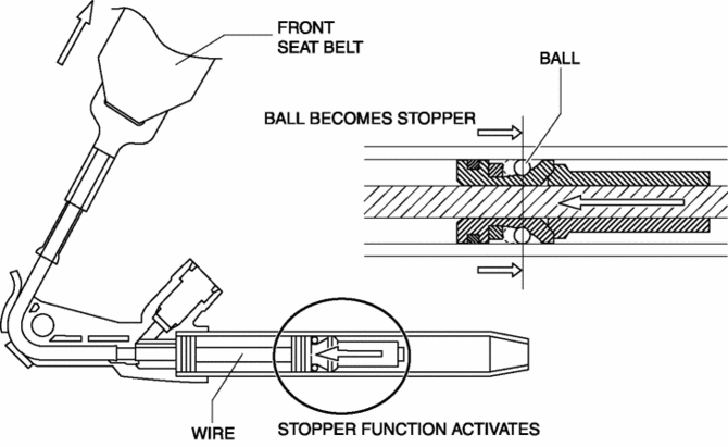
After activation
1. After operating (deploying) the pre-tensioner, the lead wire is pulled back. However the front seat belts are locked by activation of the stopper function so that the belt webbing is not released.
2. The restraint force of the seat belt is adjusted by the front seat belt load limiter mechanism, preventing injury to the driver and passenger from seat belt pressure.
Fail-safe
-
Function not equipped.
 Ion Sensor
Purpose/Function
Detects ion generation in the combustion chamber for detecting pre-ignition.
Detects ions which occur due to fuel combustion as current by applying bias
voltage to t ...
 Neutral Switch Inspection
Continuity Inspection
1. Disconnect the negative battery cable..
2. Remove the neutral switch..
3. Inspect for continuity between neutral switch No.1 terminal A and B.
If not as speci ...
Other materials:
Fully Automatic Type
Climate control information is displayed on the display.
Control Switches
AUTO switch
By pressing the AUTO switch the following functions will be automatically controlled
in accordance with the selected set temperature:
• Airflow temperature
• Amount of airflow
• Selection of airflow ...
Crankshaft Position (CKP) Sensor Inspection
Visual Inspection
CAUTION:
When foreign material such as an iron chip is on the CKP sensor, it can cause
abnormal output from the sensor because of flux turbulence and adversely affect
the engine control. Be sure there is no foreign material on the CKP sensor when
replacing.
...
Relay And Fuse Block
Purpose
Relays and fuses used by each system are grouped and housed together for
smooth inspection and replacement servicing.
Function
Relays and fuses used by each system are grouped and housed together.
Construction
Installed in the engine compartment.
...
