Mazda CX-5 Service & Repair Manual: Headlight Auto Leveling System Initialization
NOTE:
-
The AFS control module records the vehicle height while it is unoccupied by performing the headlight auto leveling system initial setting.
-
Perform headlight auto leveling system initial setting if any of the following work is performed.
-
AFS control module replacement
-
Auto leveling sensor replacement, removal/installation
-
Work that can affect vehicle height such as suspension replacement or removal/installation.
-
There are two types of procedures for headlight auto leveling system initial setting, one which uses the M-MDS and the other which does not use it.
When using the M-MDS
1. Empty the vehicle by having all occupants leave the vehicle and remove all the cargo except for the spare tire, jack and tools equipped on the vehicle.
2. Adjust the air pressure of each tire to the specified value..
3. Move the vehicle to level ground.
4. Connect the M-MDS to the DLC-2.
5. After vehicle identification, select in the following order from the M-MDS initial screen.
NOTE:
-
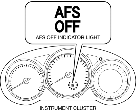
The AFS OFF indicator light continues flashing during the first initial setting, however, continue the work because it does not indicate an improper procedure.

a. “Electrical”
b. “ExteriorLighting”
c. “Headlamp”
d. “Auto Leveling Sensor”
e. “Auto Leveling Sensors Calibration”
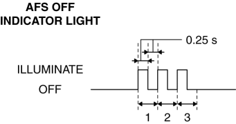
6. Verify that the AFS OFF indicator light flashes three times at 0.25 s
intervals and turns off as shown in the figure.

7. Adjust the headlight aiming..
When not using the M-MDS
CAUTION:
-
Perform Steps 3-4 within 30 s.
1. Empty the vehicle by having all occupants leave the vehicle and remove all the cargo except for the spare tire, jack and tools equipped on the vehicle.
2. Adjust the air pressure of each tire to the specified value..
3. Switch the ignition ON (engine off or on).
NOTE:
-
The AFS OFF indicator light continues flashing during the first initial setting, however, continue the work because it does not indicate an improper procedure.

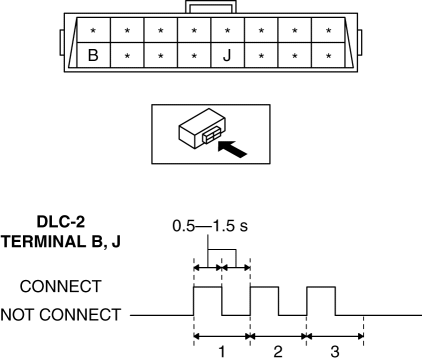
4. Using a jumper wire, connect DLC-2 terminals B and J (ground) three times at 0.5 to 1.5 s
intervals as shown in the figure.
CAUTION:
-
If the terminals are mistakenly connected, vehicle damage or fire could occur. When connecting with the jumper wire, thoroughly verify what terminals are being connected to prevent a miss-connection.

5. Verify the AFS OFF indicator light.
-
If the AFS OFF indicator light flashes three times at 0.25 s
intervals and turns off as shown in the figure, the initial setting is completed. Go to the next step.

-
If the AFS OFF indicator light continues flashing, the procedure may be performed incorrectly. Repeat the procedure from Step 1.
-
If the AFS OFF indicator light is illuminated, the headlight auto leveling system may have a malfunction. Perform the DTC inspection..
-
Repair or replace the malfunctioning area, then repeat the procedure from Step 1.
6. Adjust the headlight aiming..
 Headlight Auto Leveling System
Outline
Automatically adjusts the headlight optical axis in response to changes in
load and passenger conditions to prevent blinding of oncoming vehicles from
headlight glare and to assur ...
 Headlight Bulb Removal/Installation
Halogen Type
Headlight LO bulb
1. Disconnect the negative battery cable..
2. Disconnect the connector.
3. Rotate the headlight LO bulb in the direction of the arrow (1) shown in the
figure ...
Other materials:
Electronic Spark Advance Control [Skyactiv G 2.0]
Outline
Controls ignition to optimum timing according to engine operation conditions.
Serviceability has been improved by eliminating the necessity of ignition
timing adjustment.
The PCM determines the engine operation conditions based on input signals
from each sensor a ...
Cylinder Head
Outline
With the adoption of the rocker arm (built into needle roller bearing), the
sliding resistance has been reduced.
With the adoption of the HLA, the valve clearance is maintained at 0 mm at
all the times.
The contact point of the rocker arm and cam is lubricated by ...
Engine Transaxle Integration Control [Fw6 A EL, Fw6 Ax EL]
Outline
The TCM controls engine output torque and reduces transaxle output shaft
torque fluctuation during auto shifting, and reduces shock occurring from the
vehicle during shifting.
Construction
Operation
During auto shifting, the TCM sends the torque reduction reque ...
