Mazda CX-5 Service & Repair Manual: Hazard Warning Switch Inspection
1. Disconnect the negative battery cable..
2. Remove the decoration panel..
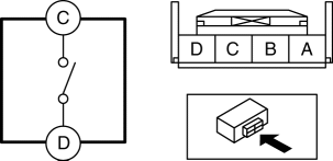
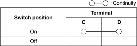
3. Verify that the continuity between the hazard warning switch terminals is as indicated in the table.


-
If the continuity is as indicated in the table, go to the next step.
-
If not as indicated in the table, replace the hazard warning switch.
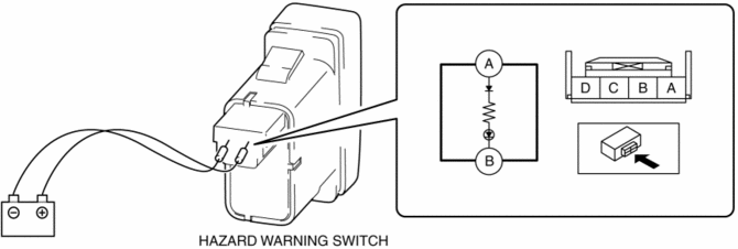
4. Apply battery voltage to hazard warning switch terminal A, and connect terminal B to ground.

5. Verify that the LED illuminates.
-
If the LED does not illuminate, replace the hazard warning switch.
 Front Fog Light Switch Inspection
1. Disconnect the negative battery cable..
2. Remove the column cover..
3. Remove the light switch..
4. Verify that the continuity between the light switch terminals is as indicated
in the tab ...
 Hazard Warning Switch Removal/Installation
1. Disconnect the negative battery cable..
2. Remove the decoration panel..
3. While pressing the hazard warning switch tab in the direction of the arrow
(1) shown in the figure, press the hazar ...
Other materials:
Rear Map Light
Purpose
The rear map lights shine light at the center of the vehicle interior.
Function
The rear map lights illuminate when the interior light switch is in the ON
position or the map light switch is turned on.
The rear map lights illuminate according to the lock condit ...
Battery [Skyactiv G 2.0]
Purpose, Function
The battery stores electricity generated by the generator. In addition, it
supplies power to electronic devices if necessary.
Construction
The battery is installed in the engine compartment. (vehicle left)
Fail-safe
Function not equipped.
...
Seat Weight Sensor Calibration [Two Step Deployment Control System]
CAUTION:
If any of the following work is performed, perform the seat weight sensor
calibration using the M-MDS.
Replacement with a new seat weight sensor
Replacement with a new seat weight sensor control module
Replacement with new passenger-side seat pa ...
