Mazda CX-5 Service & Repair Manual: Fuel Tank Inspection
WARNING:
-
Fuel is very flammable liquid. If fuel spills or leaks from the pressurized fuel system, it will cause serious injury or death and facility breakage. Fuel can also irritate skin and eyes. To prevent this, always complete the “Fuel Line Safety Procedure”, while referring to the “BEFORE SERVICE PRECAUTION”.
-
A person charged with static electricity could cause a fire or explosion, resulting in death or serious injury. Before draining fuel, make sure to discharge static electricity by touching the vehicle body.
NOTE:
-
The rollover valve and the fuel shut-off valve (built into the fuel tank) and also fuel tank leakage are inspected in this inspection.
2WD
1. Level the vehicle.
2. Complete the “BEFORE SERVICE PRECAUTION”..
3. Drain the fuel..
4. Using the following procedure:
-
6:4 split type
-
Remove the rear seat cushion..
-
4:2:4 split type
-
Set the rear seat aside as shown in the figure..
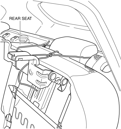
5. Partially peel back the floor mat as shown in the figure.
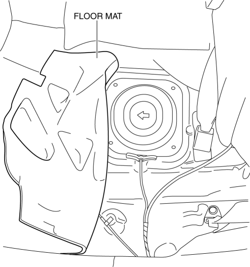
6. Remove the service hole cover.
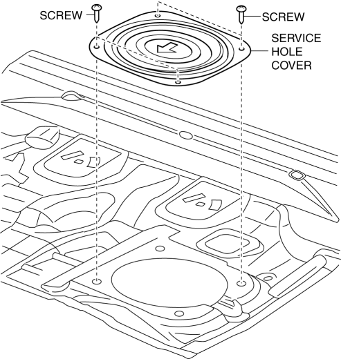
7. Disconnect the following parts:
-
Fuel pump unit connector
-
Quick release connector.
8. Remove the floor under cover (LH)..
9. Disconnect the HO2S connector.
10. Remove the TWC and HO2S as a single unit..
11. Remove the fuel tank and fuel pump unit as a single unit..
12. Perform the following procedure to verify the fuel tank airtightness.
a. Plug the fuel pump unit pipe, ports B and C.
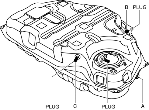
b. Apply a pressure of 3 kPa {23 mmHg, 0.9 inHg}
to port A and wait for a while.
c. Verify that there is no air flow leakage from the fuel tank.
-
If there is air flow, replace the fuel tank..
13. Plug the fuel pump unit pipe and port B.
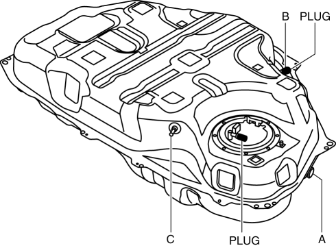
14. Level the fuel tank.
15. Apply a pressure of 3 kPa {23 mmHg, 0.9 inHg}
to port A and wait for a while.
16. With the pressure still applied, verify that there is air flow from port C and the pressure is 0—3 kPa {0—23 mmHg, 0—0.9 inHg}
.
-
If there is no air flow, replace the fuel tank..
17. Apply a pressure of -0.5 kPa {-3.8 mmHg, -0.1 inHg}
to port A and wait for a while.
18. With the pressure still applied, verify that there is air flow from port C and the pressure is -0.5—0 kPa {-3.8—0 mmHg, -0.1—0 inHg}
.
-
If there is no air flow, replace the fuel tank..
-
If there is air flow, place the fuel tank upside down.
19. Apply a pressure to port A and wait for a while.
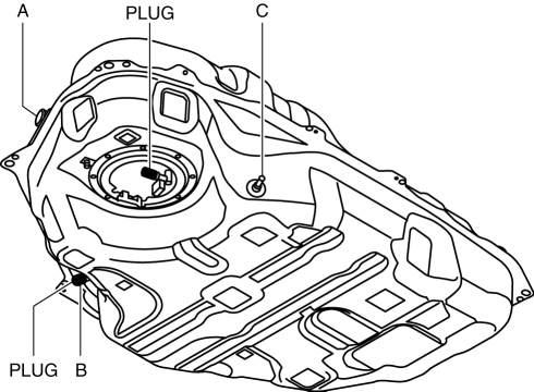
20. With the pressure still applied, verify that there is no air flow from port C.
-
If there is air flow, replace the fuel tank..
AWD
1. Level the vehicle.
2. Complete the “BEFORE SERVICE PRECAUTION”..
3. Drain the fuel..
4. Using the following procedure:
-
6:4 split type
-
Remove the rear seat cushion..
-
4:2:4 split type
-
Set the rear seat aside as shown in the figure..
Main side

Sub side
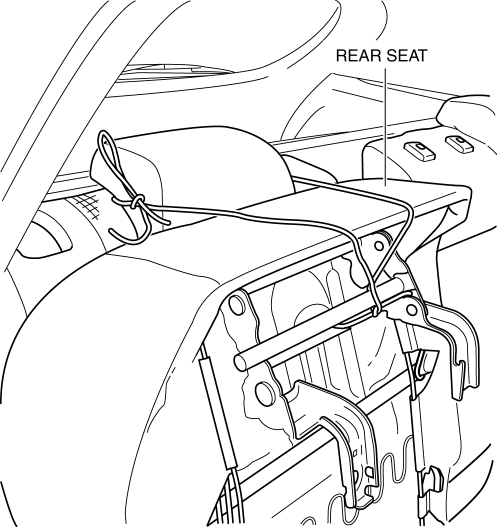
5. Partially peel back the floor mat as shown in the figure.
Main side

Sub side
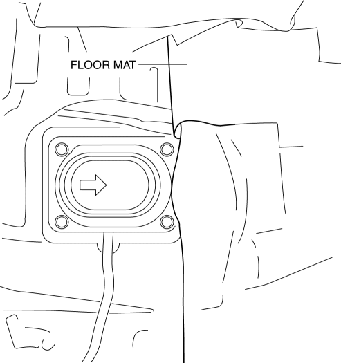
6. Remove the service hole cover.
Main side

Sub side
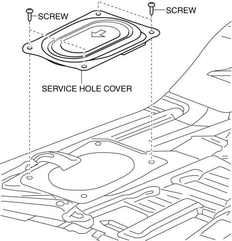
7. Disconnect the following parts:
-
Main side
-
Fuel pump unit connector
-
Quick release connector.
-
Sub side
-
Fuel gauge sender unit (sub) connector
8. Remove the floor under cover..
9. Disconnect the HO2S connector.
10. Remove the TWC and HO2S as a single unit..
11. Remove the propeller shaft..
12. Remove the fuel tank, fuel pump unit and fuel gauge sender unit (sub) as a single unit..
13. Perform the following procedure to verify the fuel tank airtightness.
a. Plug the fuel pump unit pipe, ports B and C.
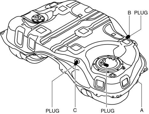
b. Apply a pressure of 3 kPa {23 mmHg, 0.9 inHg}
to port A and wait for a while.
c. Verify that there is no air flow leakage from the fuel tank.
-
If there is air flow, replace the fuel tank..
14. Plug the fuel pump unit pipe and port B.
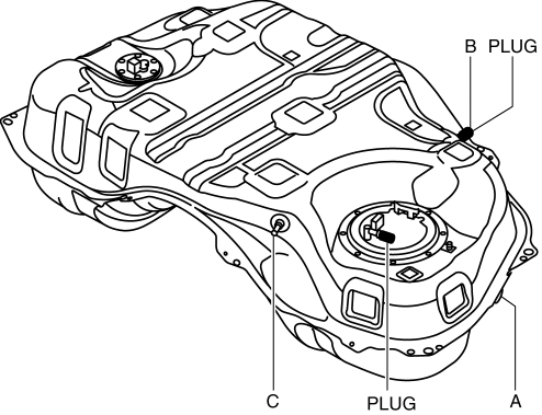
15. Level the fuel tank.
16. Apply a pressure of 3 kPa {23 mmHg, 0.9 inHg}
to port A and wait for a while.
17. With the pressure still applied, verify that there is air flow from port C and the pressure is 0—3 kPa {0—23 mmHg, 0—0.9 inHg}
.
-
If there is no air flow, replace the fuel tank..
18. Apply a pressure of -0.5 kPa {-3.8 mmHg, -0.1 inHg}
to port A and wait for a while.
19. With the pressure still applied, verify that there is air flow from port C and the pressure is -0.5—0 kPa {-3.8—0 mmHg, -0.1—0 inHg}
.
-
If there is no air flow, replace the fuel tank..
-
If there is air flow, place the fuel tank upside down.
20. Apply a pressure to port A and wait for a while.
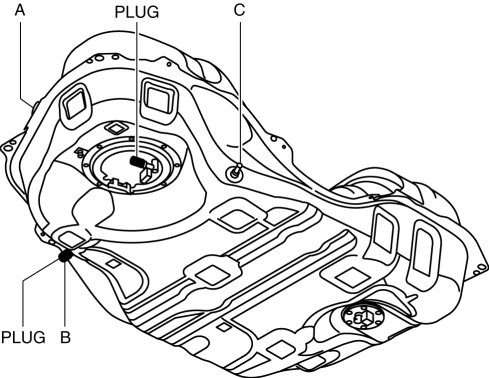
21. With the pressure still applied, verify that there is no air flow from port C.
-
If there is air flow, replace the fuel tank..
 Fuel System
Purpose, Outline
A multiple hole type fuel injector has been adopted which provides higher
fuel injection accuracy for improved fuel efficiency and output.
Piston movement-compressio ...
 Fuel Tank Removal/Installation
WARNING:
Fuel is very flammable liquid. If fuel spills or leaks from the pressurized
fuel system, it will cause serious injury or death and facility breakage. Fuel
can also irritate skin ...
Other materials:
Ignition Coil Inspection [Skyactiv G 2.0]
Ignition Coil Inspection
1. Perform the spark test and identify the malfunctioning cylinder..
2. Replace the ignition coil of the malfunctioning cylinder with that of a normal
cylinder, and perform the spark test again..
If the spark is not normal due to a malfunctioning ignition coil, ...
Electronic Control System Outline [Fw6 A EL, Fw6 Ax EL]
Outline
In the electronic control system, the TCM calculates the control content
based on signals from each type of sensor and switch to operate output parts
such as each solenoid. In consideration of suppressed shift shock, smooth driving,
and improved fuel economy, the TCM performs ...
Side Air Bag Sensor Removal/Installation [Two Step Deployment Control System]
WARNING:
Handling the side air bag sensor improperly can accidentally operate (deploy)
the air bag module, which may seriously injure you. Read the air bag system
service warnings and cautions before handling the side air bag sensor..
1. Switch the ignition to off.
2. Disconnec ...
