Mazda CX-5 Service & Repair Manual: Front Side Frame (Partial Cutting) Removal [Panel Replacement]
Symbol Mark

Removal Procedure
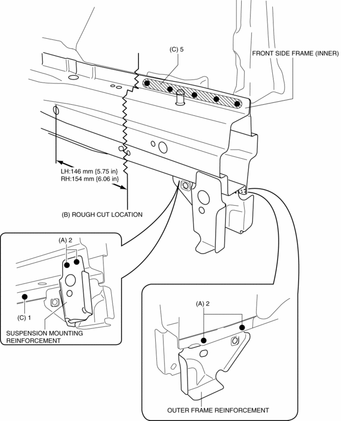
1. Drill the 4 locations indicated by (A) shown in the figure, then remove suspension mounting reinforcement and outer frame reinforcement.
2. Rough cut location indicated by (B) shown in the figure.
3. Drill the 6 locations indicated by (C) shown in the figure, then remove the front side frame (inner).

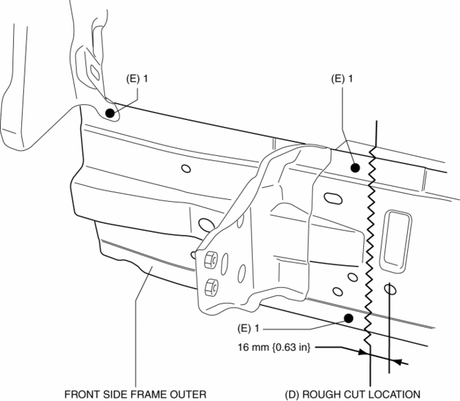
4. Rough cut location indicated by (D) shown in the figure.
5. Drill the 3 locations indicated by (E) shown in the figure.

6. Remove the front side frame (outer).
 Front Side Frame (Partial Cutting) Installation [Panel Replacement]
Symbol Mark
Installation Procedure
CAUTION:
The cut and joint area indicates the maximum size range of the installation
position.
1. Drill holes for the plug welding before inst ...
 Front Side Frame Installation [Panel Replacement]
Symbol Mark
Installation Procedure
1. When installing new parts, measure and adjust the body as necessary to conform
with standard dimensions.
2. Drill holes for the plug welding before inst ...
Other materials:
Blind Spot Monitoring (Bsm) Off Indicator Light
Purpose
The BSM OFF indicator light informs the driver that the Blind Spot Monitoring
(BSM) system is turned off or there is a malfunction in the system.
Function
The instrument cluster illuminates the BSM OFF indicator light based on the
BSM system off signal sent via a CA ...
Rain Sensor
Outline
The rain sensor detects the amount of rainfall and calculates the wiper operation
speed, and outputs a windshield wiper control signal to the front body control
module (FBCM) to perform automatic wiper operation (auto wiper system) according
to the amount of rainfall.
...
Rear Crossmember Removal/Installation [Awd]
WARNING:
Verify that the crossmember is securely supported by a jack. If the rear
crossmember falls off, it can cause serious injury or death, and damage to the
vehicle.
CAUTION:
Performing the following procedures without first removing the rear ABS wheel-speed
sensor ...
