Mazda CX-5 Service & Repair Manual: Front Fender Junction Installation [Panel Replacement]
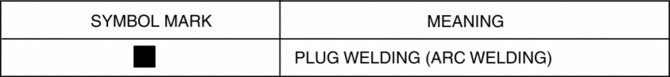
Symbol Mark
Installation Procedure
1. When installing new parts, measure and adjust the body as necessary to conform with standard dimensions.
2. Drill holes for the plug welding before installing the new parts.
3. After temporarily installing new parts, make sure the related parts fit properly.
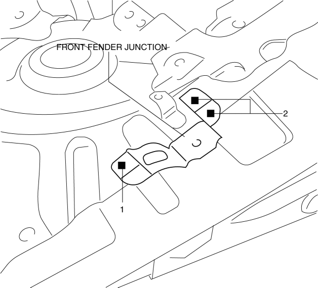
4. Plug weld the 3 locations shown in the figure.
 Electric Variable Valve Timing Relay [Skyactiv G 2.0]
Purpose, Function
The electric variable valve timing actuator relay supplies power to the electric
variable valve timing motor/driver after receiving the signal from the PCM.
Construct ...
 Front Fender Junction Removal [Panel Replacement]
Symbol Mark
Removal Procedure
1. Drill the 3 locations shown in the figure.
2. Remove the front fender junction. ...
Other materials:
Blind Spot Monitoring (Bsm) System
Outline
The blind spot monitoring (BSM) system detects vehicles approaching from
the rear blind spots, and illuminates the BSM indicator light on the outer mirror
glass. When the BSM indicator light is illuminated and the turn light switch
is turned on to the side in which the indica ...
Windshield Wiper Motor And Link Removal/Installation
1. Disconnect the negative battery cable..
2. Remove the following parts:
a. Windshield wiper arm and blade.
b. Cowl grille.
CAUTION:
Always affix protective tape to the windshield end. If the windshield wiper
motor and link contacts the windshield, it could damage the windshield. ...
Inspection Of SST (Deployment Tool) [Two Step Deployment Control System]
1. Before using the SST (49 H066 002), inspect its operation.
Inspection Procedure
1. Follow the steps below to inspect the SST (49 H066 002).
If not as indicated in the table, replace the SST (49 H066 002) because
it has a malfunction.
WARNING:
Do not use a malfu ...
