Mazda CX-5 Service & Repair Manual: Front Door Key Cylinder Switch Inspection
1. Perform the front door glass preparation..
2. Disconnect the negative battery cable..
3. Remove the following parts:
a. Inner garnish.
b. Front door trim.
c. Front door key cylinder.
d. Front door glass.
e. Front door module panel.
f. Front door latch and lock actuator.
Front Door Key Cylinder Switch Lock-Side Inspection
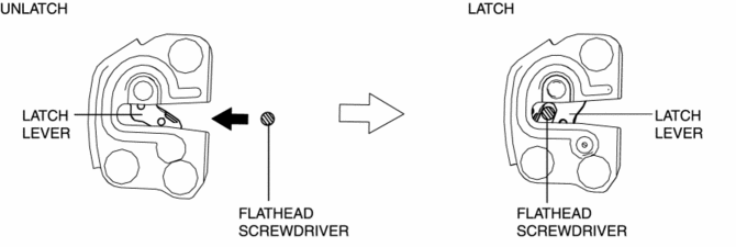
1. Press in the latch lever of the front door latch and lock actuator using a flathead screwdriver, and set it to the latched condition.
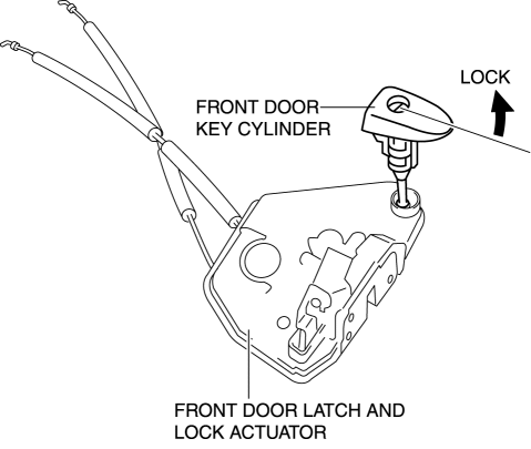
2. Rotate the front door key cylinder in the direction of the arrow until it stops to set the front door key cylinder switch to the locked condition.
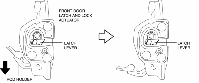
3. To verify that the switch is in the locked position, press down the rod holder in the direction of the arrow and verify that the latch lever does not move.
NOTE:
-
If the latch lever moves, the front door key cylinder switch is not in the locked position. Repeat the procedure from Step 1.
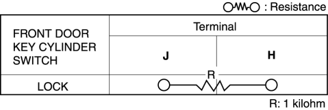
4. Verify that the continuity of the front door key cylinder is as indicated in the table.

-
If not as indicated in the table, replace the front door latch and lock actuator.
Front Door Key Cylinder Switch Unlock-Side Inspection
1. Press in the latch lever of the front door latch and lock actuator using a flathead screwdriver, and set it to the latched condition.

2. Rotate the front door key cylinder in the direction of the arrow until it stops to set the front door key cylinder switch to the unlocked condition.
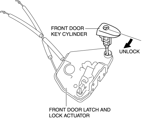
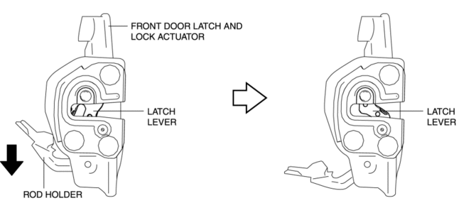
3. To verify that the switch is in the unlocked position, press down the rod holder in the direction of the arrow and verify that the latch lever moves.
NOTE:
-
If the latch lever does not move, the front door key cylinder switch is not in the unlocked position. Repeat the procedure from Step 2.
4. Verify that the continuity of the front door key cylinder is as indicated in the table.


-
If not as indicated in the table, replace the front door latch and lock actuator.
 Front Door Key Cylinder Removal/Installation
1. Disconnect the negative battery cable..
2. Remove the service hole cover.
3. Detach the screw from the front door key cylinder.
NOTE:
The screw cannot be removed because the f ...
 Front Door Latch And Lock Actuator Inspection
The following actuator and switches are integrated with the front door latch
and lock actuator.
From the actuator/switch name and operation in the following table, select
the a ...
Other materials:
Seat Track Position Sensor Removal/Installation [Two Step Deployment Control
System]
1. Switch the ignition to off.
2. Disconnect the negative battery cable and wait for 1min or more..
3. Remove the front driver’s seat..
4. Disconnect the connector from the seat track position sensor by pressing the
connector tab and pulling out the lock lever in the direction of the arro ...
Tcs Off Switch, Tcs Off Indicator Light
Purpose/Function
The TCS OFF switch, located on the dashboard, allows for optionally enabling/disabling
the TCS control at driver discretion.
The TCS OFF indicator light, built into the instrument cluster, informs the
driver that TCS control has been disabled by operation ...
Electric Variable Valve Timing Actuator Inspection
WARNING:
A hot engine can cause severe burns. Turn off the engine and wait until it
is cool before servicing.
CAUTION:
Do not disassemble the electric variable valve timing actuator because it
is a precision unit.
1. Disconnect the negative battery cable..
2. Remo ...
