Mazda CX-5 Service & Repair Manual: Front Combination Light
Purpose
-
Parts related to the front exterior lights are grouped and housed together such as the headlight, front turn/parking light, headlight leveling actuator, wiring harnesses, and connectors.
Function
-
Each light illuminates or flashes when the light switch, turn switch, or hazard switch is operated.
Construction
-
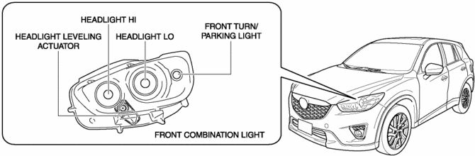
A halogen type or discharge type headlight is available for the front combination light.
Halogen type
-
The following parts are an integrated structure.
-
Headlight LO
-
Headlight HI
-
Front turn/parking light
-
Headlight leveling actuator
-
A projector type headlight has been adopted for the headlight LO.
-
A clear lens has been adopted for the front combination light.
NOTE:
-
Fogging or condensation on the inside of the front combination lights may occur, however, it is a natural phenomenon occurring as a result of a temperature difference between the interior and exterior of the front combination lights and has no effect on the light performance.
-
Fogging or condensation occurring as a natural phenomenon will dissipate when the temperature inside the front combination lights rises after the headlights are illuminated and a period of time has elapsed.
-
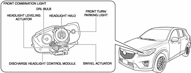
Discharge type
-
The following parts are an integrated structure.
-
Headlight HI/LO
-
DRL (Daytime running light)
-
Parking light
-
Front turn/parking light
-
Headlight leveling actuator
-
Swivel actuator
-
A projector type headlight has been adopted for the headlight.
-
The discharge headlight control module is assembled to the lower area of the front combination light.
-
A clear lens has been adopted for the front combination light.
NOTE:
-
Fogging or condensation on the inside of the front combination lights may occur, however, it is a natural phenomenon occurring as a result of a temperature difference between the interior and exterior of the front combination lights and has no effect on the light performance.
-
Fogging or condensation occurring as a natural phenomenon will dissipate when the temperature inside the front combination lights rises after the headlights are illuminated and a period of time has elapsed.
-
Operation
Headlight LO
-
Halogen type
-
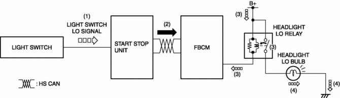
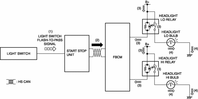
When the light switch is operated to the HEAD position, a light switch LO signal is input to the start stop unit.
-
The start stop unit sends the light switch LO signal to the front body control module (FBCM) as a CAN signal.
-
When the front body control module (FBCM) receives the light switch LO signal, it turns the headlight LO relay on.
-
When the headlight LO relay turns on, the headlight LO bulbs are illuminated.
-
Discharge type
-
Refer to the discharge headlight system..
Headlight HI
-
Halogen type
-
When the light switch is operated to the HEAD position, a light switch LO signal is input to the start stop unit.
-
The start stop unit sends the light switch LO signal to the front body control module (FBCM) as a CAN signal.
-
When the front body control module (FBCM) receives the light switch LO signal, it turns the headlight LO relay on.
-
When the headlight LO relay turns on, the headlight LO bulbs are illuminated.
-
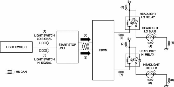
When the light switch is operated to the HI position, a light switch HI signal is input to the start stop unit.
-
The start stop unit sends the light switch HI signal to the front body control module (FBCM) as a CAN signal.
-
When the front body control module (FBCM) receives the light switch HI signal, it turns the headlight HI relay on.
-
When the headlight HI relay turns on, the headlight HI bulbs are illuminated.
-
Discharge type
-
Refer to the discharge headlight system..
Flash-to pass
-
Halogen type
-
When the light switch is operated to the passing position, a light switch passing signal is input to the start stop unit.
-
The start stop unit sends the light switch passing signal to the front body control module (FBCM) as a CAN signal.
-
When the front body control module (FBCM) receives the light switch passing signal, it turns the headlight LO and HI relays on.
-
When the headlight LO and HI relays turn on, the headlight LO and HI bulbs are illuminated.
-
Discharge type
-
Refer to the discharge headlight system..
DRL system
-
Refer to the DRL system..
Parking light
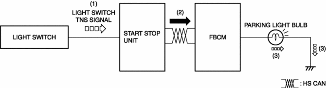
1. When the light switch is operated to the TNS position, a light switch TNS signal is input to the start stop unit.
2. The start stop unit sends the light switch TNS signal to the front body control module (FBCM) as a CAN signal.
3. When the front body control module (FBCM) receives the light switch TNS signal, the parking light bulbs are illuminated.
Front turn light
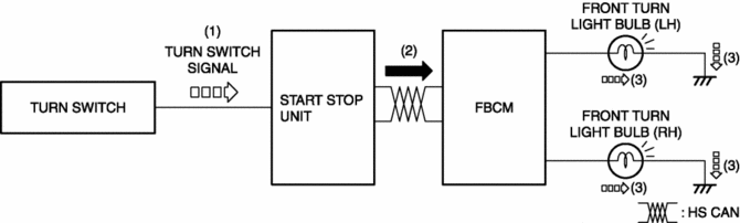
1. When the turn switch is operated to the LH or RH position, a turn switch LH or RH signal is input to the start stop unit.
2. The start stop unit sends the turn switch LH or RH signal to the front body control module (FBCM) as a CAN signal.
3. When the front body control module (FBCM) receives the turn switch LH or RH signal, the front turn light bulb (LH) or (RH) is illuminated.
Front turn light (hazard warning)
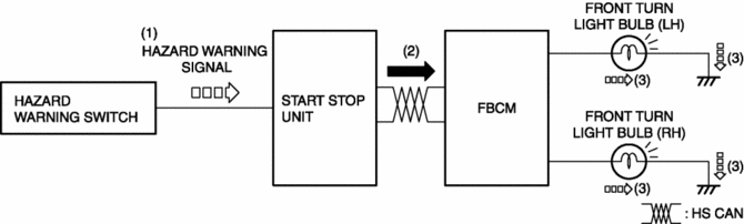
1. When the hazard warning switch is turned on, a hazard signal is input to the start stop unit.
2. The start stop unit sends a hazard warning signal to the front body control module (FBCM).
3. When the front body control module (FBCM) receives the hazard warning signal, the front turn lights (RH) and (LH) flash.
Headlight leveling actuator
-
Refer to the headlight leveling actuator..
Swivel actuator (with headlight auto leveling system)
-
Refer to the swivel actuator..
Fail-safe
-
Function not equipped.
 Exterior Lighting Systems
Outline
Projector type headlights have been adopted to the front combination lights.
Auto-light system has been adopted in which TNS and headlights automatically
and optimally illumi ...
 Front Combination Light Disassembly/Assembly
1. Disassemble in the order shown in the figure.
Halogen type
1
Short cord
(See Short Cord Removal Note.)
2
Parking/Front turn light bulb
...
Other materials:
Passenger Compartment Temperature Sensor [Full Auto Air Conditioner]
Purpose
The passenger compartment temperature sensor detects the cabin temperature.
Function
The passenger compartment temperature sensor converts the detected temperature
to an electric signal.
Construction
A thermistor-type passenger compartment temperature sens ...
Generator Disassembly/Assembly [Skyactiv G 2.0]
CAUTION:
Melt the solder quickly, otherwise the diodes (rectifier) and regulator will
be damaged by excessive heat.
1. Disassemble in the order indicated in the table.
2. Assemble in the reverse order of disassembly.
1
Rotor component
...
Starting the Engine
WARNING
Radio waves from the key may affect medical devices such as pacemakers: Before
using the key near people who use medical devices, ask the medical device manufacturer
or your physician if radio waves from the key will affect the device.
NOTE
• The key must be carried because the
ke ...
