
Mazda CX-5 Service & Repair Manual: Engine Mount Disassembly/Assembly
No.1 Engine Mount (2WD)
1. Remove the front under cover No.2..
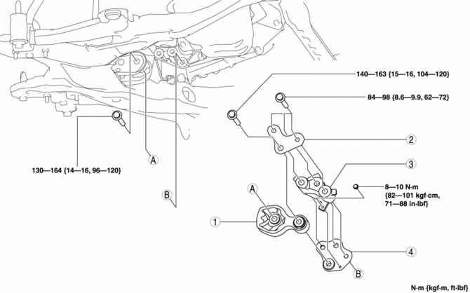
2. Remove in the order indicated in the table.
3. Install in the reverse order of removal.
|
1 |
No.1 engine mount rubber (See No.1 engine mount rubber removal note (2WD).) (See No.1 engine mount installation note (2WD).) |
|
2 |
Bracket plate (No.1) (See No.1 engine mount installation note (2WD).) |
|
3 |
No.1 engine mount bracket (See No.1 engine mount installation note (2WD).) |
|
4 |
Bracket plate (No.2) (See No.1 engine mount installation note (2WD).) |
No.1 engine mount rubber removal note (2WD)
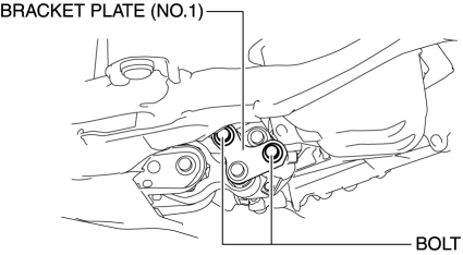
1. Loosen the bolts shown in the figure.
NOTE:
-
The bracket plate (No.1) can move slightly by loosening the bolts shown in the figure and the No.1 engine mount rubber can be easily removed.
2. Remove the No.1 engine mount rubber.
No.1 engine mount installation note (2WD)
1. Install the No.1 engine mount bracket, plate (No.1), and plate (No.2) and temporarily tighten the installation bolts.
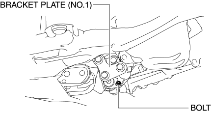
2. Tighten the bolt shown in the figure.
-
Tightening torque
-
8—10 N·m {82—101 kgf·cm, 71—88 in·lbf}
3. Install the No.1 engine mount rubber and temporarily tighten the installation bolts.
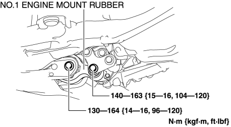
4. Tighten the No.1 engine mount bracket, plate (No.1) and plate (No.2) installation bolts in the order shown in the figure.

-
Tightening torque
-
84—98 N·m {8.6—9.9 kgf·m, 62—72 ft·lbf}
5. Tighten the No.1 engine mount rubber installation bolts.
No.1 Engine Mount (AWD)
NOTE:
-
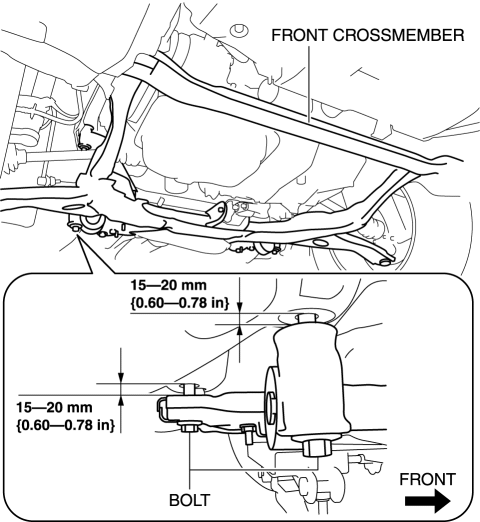
When removing the No.1 engine mount rubber for AWD vehicles, loosen the front crossmember installation bolts and perform the procedure with the front crossmember component lowered to 15—20 mm {0.60—0.78 in}.
-
When removing the No.1 engine mount bracket for AWD vehicles, perform the procedure with the front crossmember component and transfer completely removed from the vehicle.
1. Remove the front under cover No.1 and front under cover No.2..
2. Set the front mudguard away from the front crossmember and front bumper..
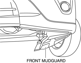
3. Remove the splash shield..
4. Remove in the order indicated in the table.
5. Install in the reverse order of removal.
6. Inspect the front wheel alignment..
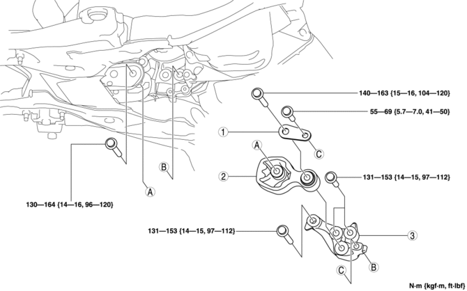
|
1 |
Bracket plate (See No.1 engine mount rubber, bracket plate installation note (AWD).) |
|
2 |
No.1 engine mount rubber (See No.1 engine mount rubber removal note (AWD).) (See No.1 engine mount rubber, bracket plate installation note (AWD).) |
|
3 |
No.1 engine mount bracket (See No.1 engine mount bracket removal note (AWD).) (See No.1 engine mount bracket installation note (AWD).) |
No.1 engine mount rubber removal note (AWD)
1. Remove the joint bolt (steering gear side) and disconnect the steering shaft from the steering gear and linkage..
2. Disconnect the front crossmember extension.

3. Remove the insulator shown in the figure.
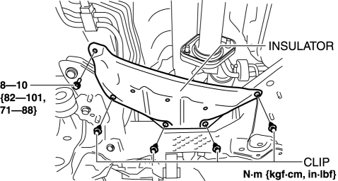
4. Disconnect the hanger rubber from the front crossmember and set it aside.
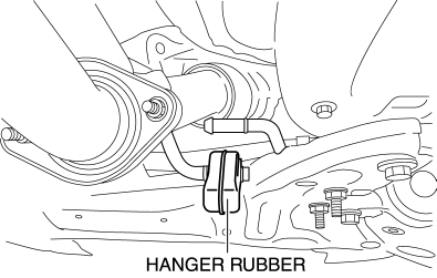
5. Disconnect the front stabilizer link (front stabilizer side)..
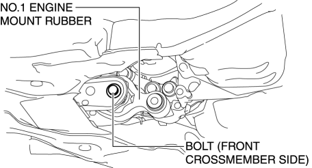
6. Remove the No.1 engine mount rubber installation bolt (front crossmember side).
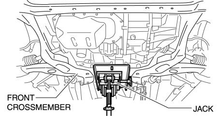
7. Support the front crossmember component using a jack.
8. Loosen the front crossmember installation bolts (8) and lower the front crossmember component to 15—20 mm {0.60—0.78 in}.
NOTE:
-
To remove the No.1 engine mount, lower the front crossmember component to make clearance between the component and transfer.
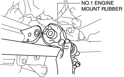
9. Remove the No.1 engine mount rubber.
No.1 engine mount bracket removal note (AWD)
1. Remove the front crossmember component and No.1 engine mount rubber as a single unit..
2. Remove the exhaust manifold..
3. Remove the transfer..
4. Remove the No.1 engine mount bracket.
No.1 engine mount bracket installation note (AWD)
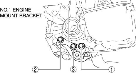
1. Install the No.1 engine mount bracket and tighten the bolts in the order shown in the figure.
-
Tightening torque
-
131—153 N·m {14—15 kgf·m, 97—112 ft·lbf}
2. Install in the reverse order of removal.
No.1 engine mount rubber, bracket plate installation note (AWD)
1. Install the No.1 engine mount rubber to the front crossmember.
2. Tighten the front crossmember installation bolts..
3. Remove the jack.
4. Tighten the No.1 engine mount rubber installation bolts.
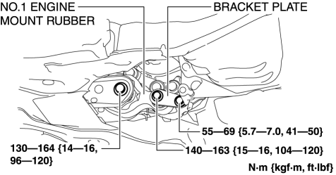
5. Install in the reverse order of removal.
No.3 Engine Mount
CAUTION:
-
Slots have been adopted for the No.3 engine mount installation holes. If the No.3 engine mount is deviated from the original position when installing the No.3 engine mount, engine noise or vibration could increase. Before removing the No.3 engine mount, place alignment marks on the No.3 engine mount and body so that they can be assembled to the same positions as before removal.
1. Disconnect the negative battery cable..
2. Remove the plug hole plate..
3. Remove in the order indicated in the table.
4. Install in the reverse order of removal.
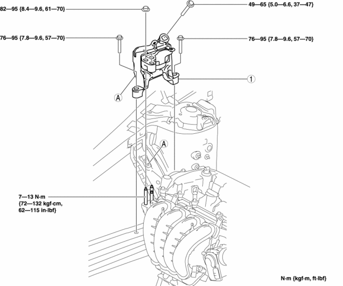
|
1 |
No.3 engine mount (See No.3 engine mount removal note.) (See No.3 engine mount installation note.) |
No.3 engine mount removal note
1. Remove the clips shown in the figure and set the ground cable aside.
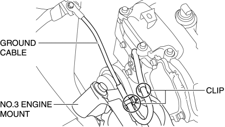
2. Remove the front under cover No.2..
CAUTION:
-
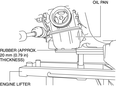
To prevent deformation of the oil pan, support the engine using the following methods.
-
When using an engine lifter, insert rubber of appropriate size (approx. 20 mm {0.79 in} thickness) between the engine lifter and the oil pan to support the oil pan.
-
When using a garage jack, place rubber of appropriate size (approx. 20 mm {0.79 in} thickness) on a batten which is large enough to cover the oil pan to support the oil pan.
3. Before removing the No.3 engine mount, support the engine (oil pan) using a commercially available engine lifter or garage jack.
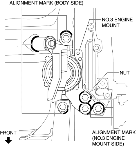
4. Place alignment marks on the locations shown in the figure so that they can be assembled to the same positions as before removal.
NOTE:
-
Paint so that the No.3 engine mount is framed on the body side and the outline of the nut is framed on the No.3 engine mount side.
5. Remove the No.3 engine mount.
No.3 engine mount installation note
NOTE:
-
When replacing the No.3 engine mount, place a mark at the same position as the one placed before removal.
-
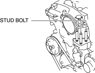
If the No.3 engine mount nut is loosened, tighten the stud bolts for the No.3 engine mount bracket because they may be loosened.
1. Tighten the No.3 engine mount stud bolts.
-
Tightening torque
-
7—13 N·m {72—132 kgf·cm, 62—115 in·lbf}
2. Temporarily tighten the No.3 engine mount installation bolts and nuts using the following procedure:
a. Align the alignment marks on the body side and No.3 engine mount, and temporarily tighten the bolts shown in the figure.
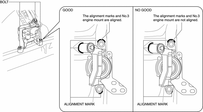
b. Temporarily tighten the nuts shown in the figure while aligning the alignment marks of the No.3 engine mount and nuts.
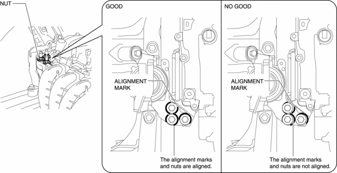
NOTE:
-
If the alignment marks are not aligned, align the alignment marks while slightly moving the engine and temporarily tighten the nuts.
3. Tighten the No.3 engine mount installation bolts and nuts in the order shown in the figure.
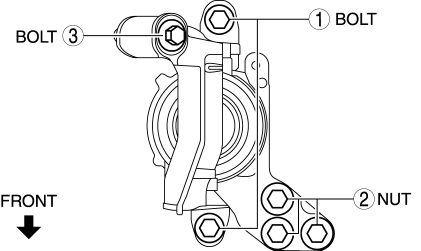
|
No. |
Tightening torque |
|
1 |
76—95 N·m {7.8—9.6 kgf·m, 57—70 ft·lbf} |
|
2 |
82—95 N·m {8.4—9.6 kgf·m, 61—70 ft·lbf} |
|
3 |
49—65 N·m {5.0—6.6 kgf·m, 37—47 ft·lbf} |
4. Remove the engine lifter or garage jack.
5. Install in the reverse order of removal.
No.4 Engine Mount
CAUTION:
-
Slots have been adopted for the No.4 engine mount bracket installation holes. If the No.4 engine mount bracket is deviated from the original position when installing the No.4 engine mount bracket, engine noise or vibration could increase. Before removing the No.4 engine mount bracket, place alignment marks on the No.4 engine mount bracket so that they can be assembled to the same positions as before removal.
1. Disconnect the negative battery cable..
2. Remove the air cleaner, air hose and fresh air duct as a single unit..
3. Remove the battery tray and PCM component..
4. Remove in the order indicated in the table.
5. Install in the reverse order of removal.
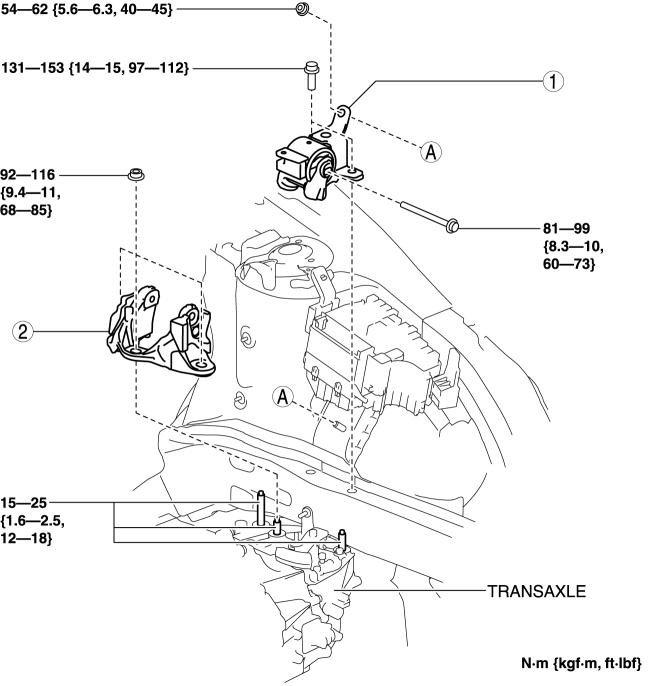
|
1 |
No.4 engine mount rubber (See No.4 engine mount rubber removal note.) (See No.4 engine mount rubber installation note.) |
|
2 |
No.4 engine mount bracket (See No.4 engine mount bracket removal note.) (See No.4 engine mount bracket installation note.) |
No.4 engine mount rubber removal note
1. Remove the clips shown in the figure and set the wiring harness protector aside.
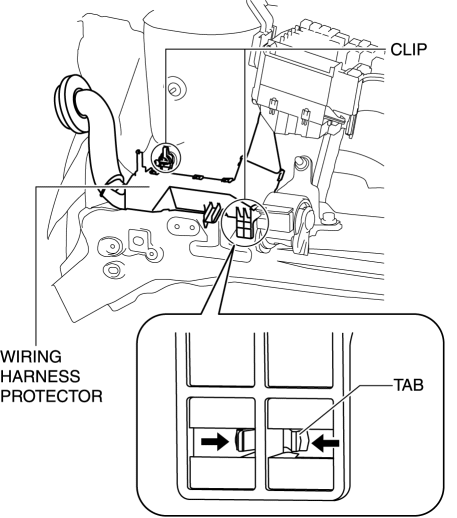
2. Remove the front under cover No.2..
CAUTION:
-
To prevent damage of the transaxle, support the transaxle using the following methods.
-
MTX: Support the clutch housing using a batten of appropriate size.
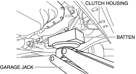
-
ATX: Place rubber of appropriate size (approx. 20 mm {0.79 in} thickness) on a batten which is large enough to cover the oil pan to support the oil pan.
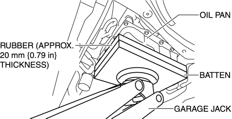
3. Before removing the No.4 engine mount rubber, support the transaxle using a commercially available engine lifter or garage jack.
4. Remove the No.4 engine mount rubber.
No.4 engine mount bracket removal note
1. Remove the bolt shown in the figure and set the ground cable aside.
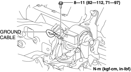
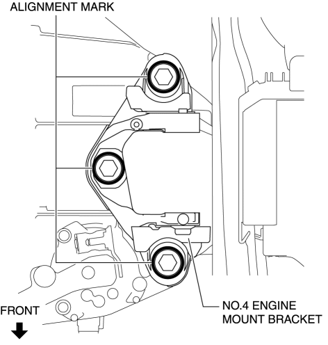
2. Place alignment marks on the locations shown in the figure so that they can be assembled to the same positions as before removal.
NOTE:
-
Paint so that the outline of the nut is framed on the bracket side.
3. Remove the No.4 engine mount bracket.
No.4 engine mount bracket installation note
NOTE:
-
When replacing the No.4 engine mount bracket, place a mark at the same position as the one placed before removal.
-
If the No.4 engine mount bracket nut is loosened, tighten the stud bolts for the transaxle because they may be loosened.
1. Tighten the stud bolts for the transaxle.
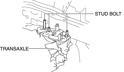
-
Tightening torque
-
15—25 N·m {1.6—2.5 kgf·m, 12—18 ft·lbf}
2. Align the alignment marks on the No.4 engine mount bracket and nuts, and temporarily tighten the nuts shown in the figure.
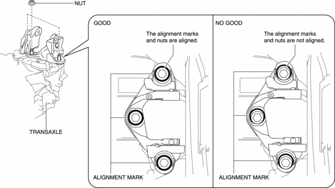
3. Tighten the No.4 engine mount bracket installation nuts in the order shown in the figure.
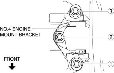
-
Tightening torque
-
92—116 N·m {9.4—11 kgf·m, 68—85 ft·lbf}
4. Install the ground cable to the No.4 engine mount bracket.
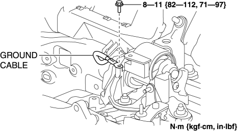
-
Tightening torque
-
8—11 N·m {82—112 kgf·cm, 71—97 in·lbf}
No.4 engine mount rubber installation note
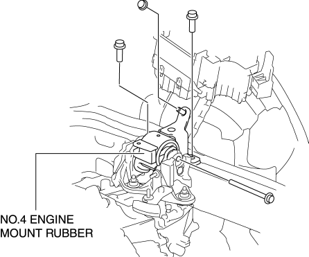
1. Install the No.4 engine mount rubber and temporarily tighten the bolts and nut shown in the figure.
2. Tighten the No.4 engine mount rubber installation bolts and nut in the order shown in the figure.
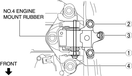
|
No. |
Tightening torque |
|
1, 2 |
131—153 N·m {14—15 kgf·m, 97—112 ft·lbf} |
|
3 |
54—62 N·m {5.6—6.3 kgf·m, 40—45 ft·lbf} |
|
4 |
81—99 N·m {8.3—10 kgf·m, 60—73 ft·lbf} |
3. Remove the engine lifter or garage jack.
4. Install in the reverse order of removal.
 Motor Mounts
...
 Engine Mount
Purpose, Function
The engine mount secures the engine and transaxle to the vehicle body, reducing
vibration and noise.
Construction
The three points at the engine front (No.3 en ...
Other materials:
Air Intake Actuator [Manual Air Conditioner]
Purpose
The air intake actuator moves the air intake door in the blower unit to switch
the air intake port.
Function
The air intake actuator drives the motor based on the signal from the climate
control unit and moves the air intake door to the FRESH or REC position.
...
Front ABS Wheel Speed Sensor Inspection
Sensor Output Value Inspection
CAUTION:
Resistance inspection using other testers may cause damage to the ABS wheel-speed
sensor internal circuit. Be sure to use the M-MDS to inspect the ABS wheel-speed
sensor.
1. Switch the ignition to off.
2. Connect the M-MDS to the DLC-2. ...
Intermediate Shaft Removal/Installation
WARNING:
The steering column (EPS motor) temperature increases directly after continuous
turning of the steering mechanism which could cause burns if it is touched.
Before performing any servicing, verify that the steering column has cooled
off.
1. Rotate the steering wheel un ...
