Mazda CX-5 Service & Repair Manual: Center Pillar Removal [Panel Replacement]
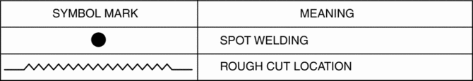
Symbol Mark
Removal Procedure
CAUTION:
-
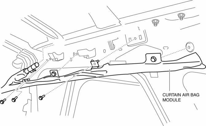
Remove the curtain air bag module to prevent damage before servicing.
Front-side
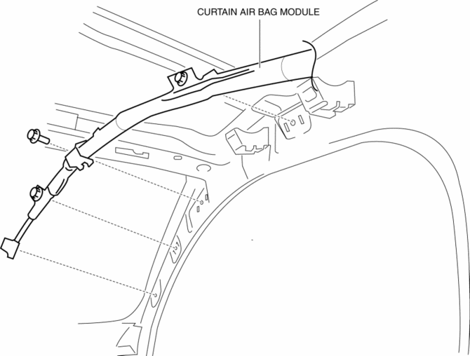
Rear-side
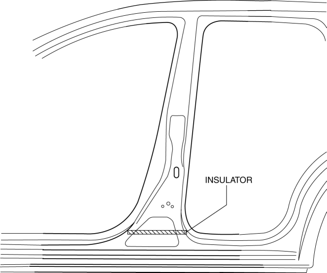
CAUTION:
-
Avoid cutting with a blowtorch or similar tools as the insulator (shaded area) is flammable.
1. Rough cut the area locations indicated by (A).
2. Drill the 84 locations indicated by (B) shown in the figure then remove the cabin side outer frame (outer center pillar).
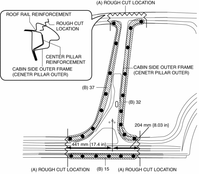
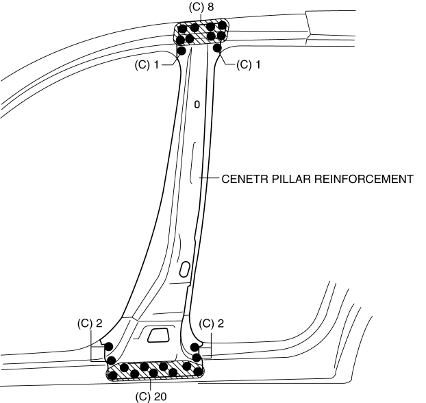
3. Drill the 34 locations indicated by (C) shown in the figure then remove the center pillar reinforcement.
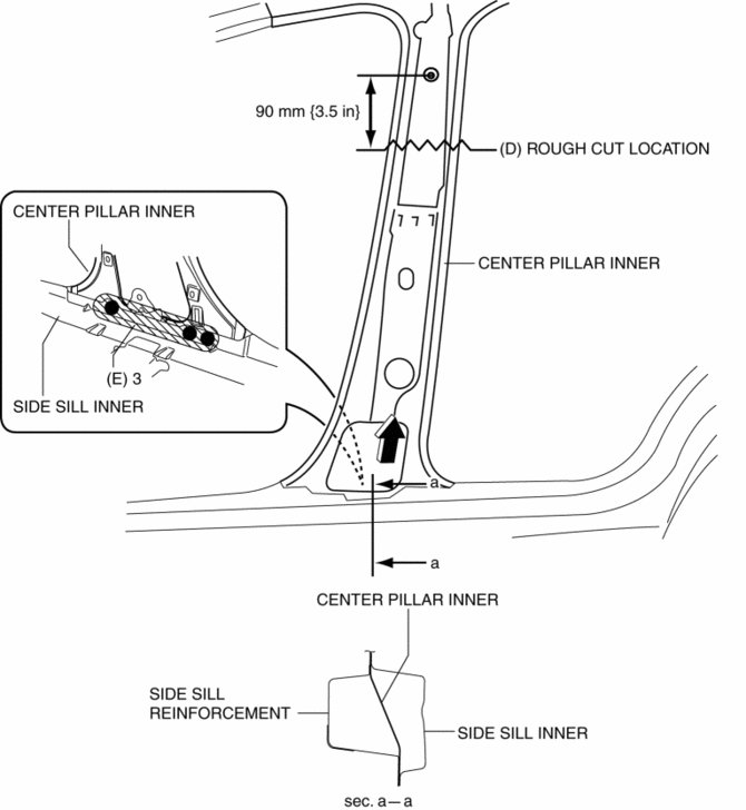
4. Rough cut the area locations indicated by (D).
5. Drill the 3 locations indicated by (E) shown in the figure.
6. Pull the inner center pillar in the direction of arrow shown in the figure, then remove it from between the inner side sill and side sill reinforcement.
 Center Pillar Installation [Panel Replacement]
Symbol Mark
Installation Procedure
1. When installing new parts, measure and adjust the body as necessary to conform
with standard dimensions.
2. Drill holes for the plug welding before inst ...
 Construction Standard Values [Construction Standard Values]
Front view
No.
Measurement part
Standard values (mm {in})
Maximum values (mm {in})
Minimum values (mm {in})
Side ...
Other materials:
Keyless Antenna [Advanced Keyless Entry System]
Purpose
Outputs a request signal and specifies the remote transmitter location.
Function
The keyless antenna outputs request signals to the inside and outside of
the vehicle based on the signals from the LF control unit.
Construction, Operation
The antennas for re ...
Wheel Hub, Steering Knuckle Removal/Installation
CAUTION:
Performing the following procedures without first removing the ABS wheel-speed
sensor may possibly cause an open circuit in the wiring harness if it is pulled
by mistake. Before performing the following procedures, disconnect the ABS wheel-speed
sensor connector (axle sid ...
Floor Mat
WARNING
Make sure the floor mats are hooked on the retention pins to prevent them from
bunching up under the foot pedals:
Using a floor mat that is not secured is dangerous as it will interfere with
the accelerator and brake pedal operation, which could result in an accident.
Do not install t ...
