
Mazda CX-5 Service & Repair Manual: Blind Spot Monitoring (Bsm) Control Module Removal/Installation
1. Disconnect the negative battery cable..
2. Remove the rear combination light..
3. Remove the rear bumper..
4. Disconnect the connector.
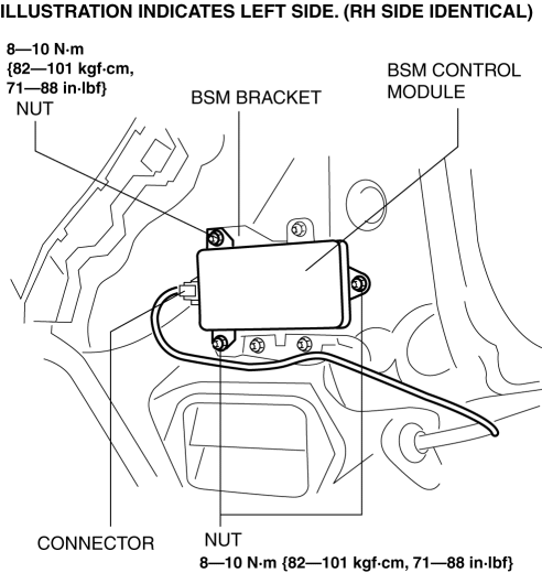
5. Remove the nuts.
6. Remove the BSM control module.
7. Install in the reverse order of removal.
8. Perform the BSM radar test..
CAUTION:
-
If the BSM control module is replaced, not performing the BSM radar test will cause a deviation in the radar emission angle which could result in the system not detecting a vehicle approaching from the rear correctly. If the BSM control module is replaced, perform the BSM radar test.
 Blind Spot Monitoring (Bsm) Control Module Inspection
1. Disconnect the negative battery cable..
2. Remove the rear combination light..
3. Remove the rear bumper..
4. Connect the negative battery cable..
5. Verify that the voltages of each of the ...
 Blind Spot Monitoring (Bsm) Off Indicator Light
Purpose
The BSM OFF indicator light informs the driver that the Blind Spot Monitoring
(BSM) system is turned off or there is a malfunction in the system.
Function
The instrument ...
Other materials:
Front Door Checker Removal/Installation
CAUTION:
When the front door checker securing bolts are removed, the front door may
open until it contacts the front fender panel causing the front door and the
front fender panel to be damaged. Before removing the front door, overlap and
adhere the protective tape to the position s ...
Steering Abbreviations
AAS
Active Adaptive Shift
ABS
Antilock Brake System
ABDC
After Bottom Dead Center
ACC
Accessories
AFS
Adaptive Front Lighting System
ALC
...
Ignition Coil/Ion Sensor Removal/Installation [Skyactiv G 2.0]
1. Disconnect the negative battery cable..
2. Remove the plug hole plate..
3. Remove in the order indicated in the table.
4. Install in the reverse order of removal.
1
Connector
2
Ignition coil
...
