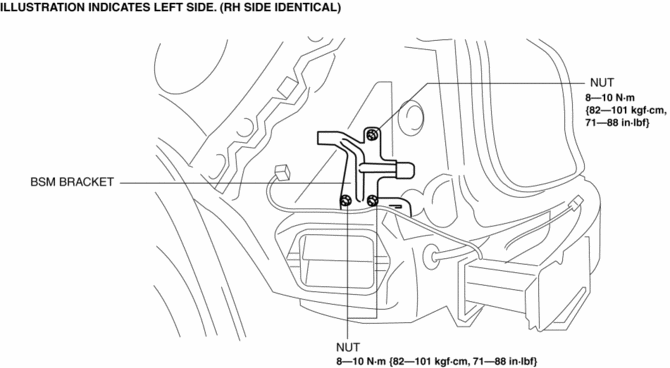
Mazda CX-5 Service & Repair Manual: Blind Spot Monitoring (Bsm) Bracket Removal/Installation
1. Disconnect the negative battery cable..
2. Remove the following parts:
a. Rear combination lights.
b. Rear bumper.
c. BSM control module.
3. Remove the nuts.

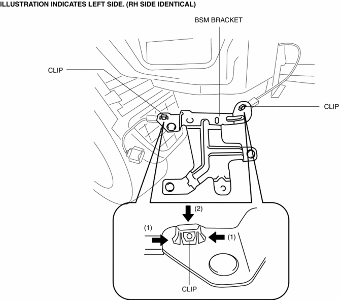
4. While pressing the clip tabs in the direction of the arrows (1) shown in the figure, press the clip in the direction of the arrow (2) to detach the clip tabs from the bracket.

5. Detach the clip.
6. Remove the BSM bracket.
7. Install in the reverse order of removal.
8. Perform the BSM radar test..
CAUTION:
-
If the BSM bracket is replaced, not performing the BSM radar test will cause a deviation in the radar emission angle which could result in the system not detecting a vehicle approaching from the rear correctly. If the BSM bracket is replaced, perform the BSM radar test.
 Active Command Modes Inspection [Blind Spot Monitoring (Bsm)]
1. Connect the M-MDS to the DLC-2.
2. After the vehicle is identified, select the following items from the initialization
screen of the M-MDS.
a. Select “DataLogger”.
b. Select ‚ÄúModules‚ ...
 Blind Spot Monitoring (Bsm) Control Module
Purpose
Controls the blind spot monitoring (BSM) system.
Function
The BSM control module emits microwaves to detect an oncoming vehicle's position
and speed information via ...
Other materials:
Air Bag Module And Pre Tensioner Seat Belt Deployment Procedures [Standard Deployment
Control System]
WARNING:
A live (undeployed) air bag module or pre-tensioner seat belt may accidentally
operate (deploy) when it is disposed of and cause serious injury. Do not dispose
of a live (undeployed) air bag module or pre-tensioner seat belt. If the SSTs
(Deployment tool and Adapter harness ...
Front Fog Light Removal/Installation
1. Disconnect the negative battery cable..
2. Remove the screws and bolt.
3. Pull up the front under cover No.1 and remove the mudguard screw shown in
the figure.
4. Disconnect the connector.
5. While pressing the clip tab in the direction of the arrow (1) shown in the
figure ...
Oil Jet Valve
Purpose, Function
The oil jet valve injects engine oil on the back of the piston to cool the
piston.
Construction
The oil jet valve is installed into the cylinder block.
The oil jet valve is built into the check ball and spring.
Operation
1. When ...
