Mazda CX-5 Service & Repair Manual: Automatic Transaxle Shift Mechanism Removal/Installation
Selector Lever Removal/Installation
1. Disconnect the negative battery cable..
2. Remove the front console..
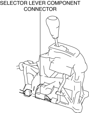
3. Disconnect the selector lever component connector.
4. Remove the selector cable (selector lever side)..
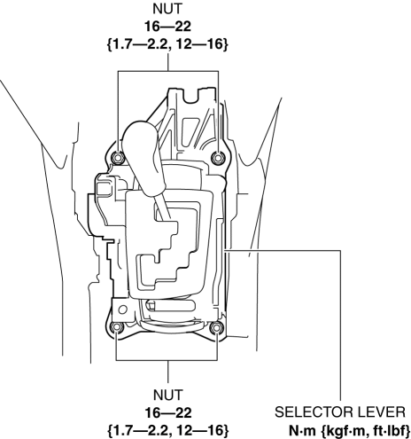
5. Remove the nuts from the selector lever.
6. Remove the knob.
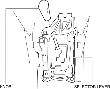
7. Remove the selector lever.
8. Install in the reverse order of removal.
Selector Cable Removal/Installation
1. Disconnect the negative battery cable..
2. Perform the following procedure to remove the selector cable (selector lever side).
a. Remove the front console..
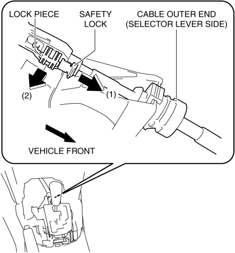
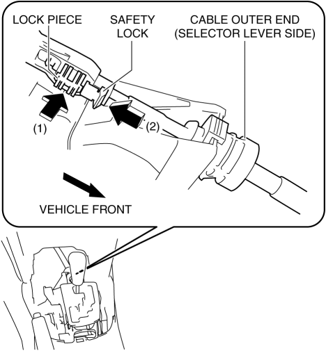
b. Pull out the safety lock in the direction of the arrow (1) shown in the figure, pull out the lock piece in the direction of the arrow (2) shown in the figure, and release the lock..
c. While pressing the cable outer end tab (selector lever side) in the direction of the arrow (3) shown in the figure, lift up cable outer end (selector lever side) in the direction of the arrow (4) shown in the figure to detach the cable outer end tab (selector lever side) from the bracket.
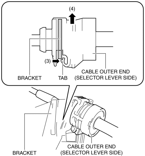
d. Remove the cable outer end (selector lever side) from the bracket.
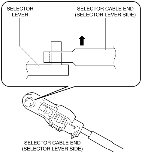
e. Remove the selector cable end (selector lever side) from the selector lever.
3. Perform the following procedure to remove the selector cable (transaxle side).
a. Remove the air cleaner case..
b. Remove the battery tray..
c. While pressing the bracket tab in the direction of the arrow (5) shown in the figure, lift up the cable outer end (transaxle side) in the direction of the arrow (6) shown in the figure to detach the bracket tab from the cable outer end (transaxle side).
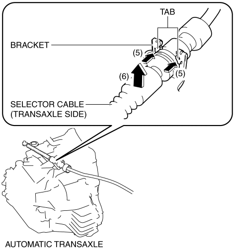
d. Remove the cable outer end (transaxle side) from the bracket..
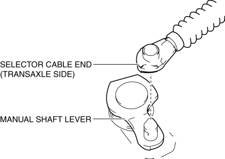
e. Remove the clip from the selector cable end (transaxle side).
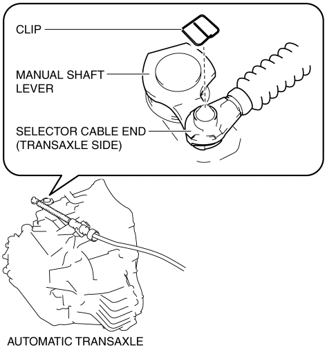
f. Remove the selector cable end (transaxle side) from the manual shaft lever.
4. Remove the side wall..
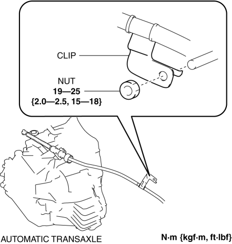
5. Remove the clip as shown in the figure and remove the nut.
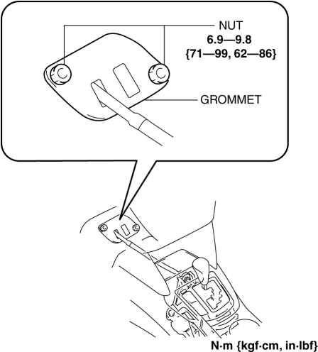
6. Remove the grommet as shown in the figure and remove the nuts.
7. Install in the reverse order of removal.
Selector Illumination Bulb Removal/Installation
1. Disconnect the negative battery cable..
2. Remove the shift panel..
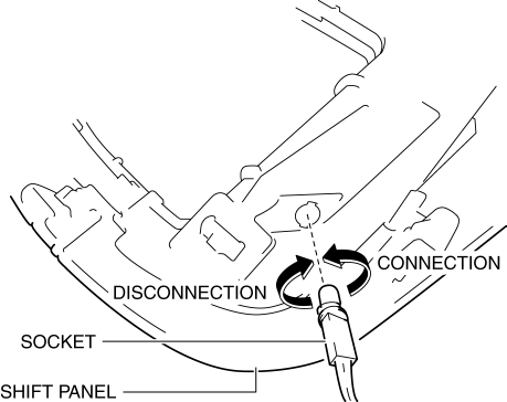
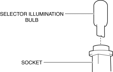
3. Remove the socket from the shift panel.
4. Remove the selector illumination bulb from the socket.
5. Install in the reverse order of removal.
Selector Cable Adjustment
1. Disconnect the negative battery cable..
2. Remove the shift panel..
3. Remove the screws from the bracket.
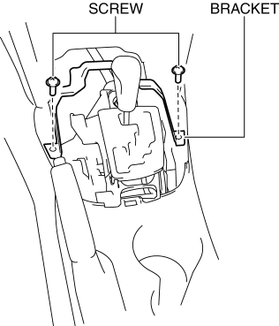
4. Remove the bracket from the rear console.
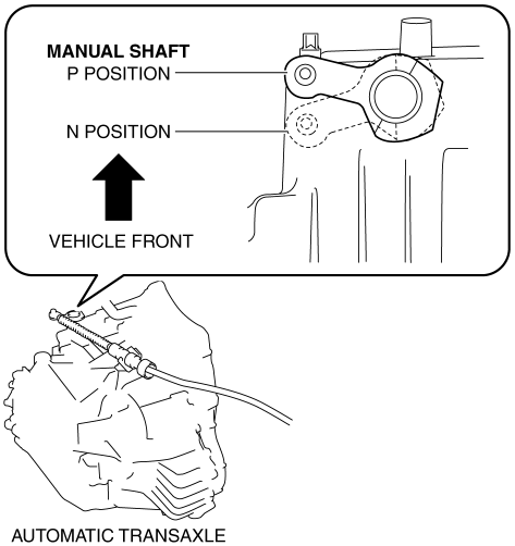
5. Shift the selector lever to the P position.
6. Pull out the safety lock in the direction of the arrow (1) shown in the figure, pull out the lock piece in the direction of the arrow (2) shown in the figure, and release the lock..
7. Set the manual shaft to the P position.
8. Press in the lock piece in the direction of the arrow (1) shown in the figure, press in the safety lock in the direction of the arrow (2) shown in the figure, and lock it.
9. Perform the procedure in the reverse order of Step 1 to 4 to install the removed part.
10. Perform the selector lever inspection..
Selector Cable (Selector Lever Side) Installation Note
1. Verify that the selector lever is in the P position.
2. Verify that the manual shaft is in the P position.
3. Press in the lock piece in the direction of the arrow (1) shown in the figure, press in the safety lock in the direction of the arrow (2) shown in the figure, and lock it.
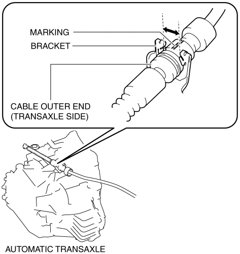
Cable Outer End (Transaxle Side) Installation Note
1. Assemble the cable outer end (transaxle side) to the bracket so that the marking is in the area of the arrow shown in the figure.
 Automatic Transaxle Removal/Installation [Fw6 Ax EL]
CAUTION:
Performing the following procedures without first removing the front ABS
wheel-speed sensor may possibly cause an open circuit in the harness if it is
pulled by mistake. Before ...
 Automatic Transaxle Shift Mechanism [Fw6 A EL, Fw6 Ax EL]
Outline
A sport AT-type shift mechanism has been adopted for all models.
An electric shift-lock system has been adopted to prevent driver mis-operation.
A manual shift-lock rele ...
Other materials:
One Way Clutch [Fw6 A EL, Fw6 Ax EL]
Purpose/Function
The one-way clutch operates in 1GR and suppresses the counterclockwise rotation
of the front internal gear (as viewed from torque converter side).
Construction
The one-way clutch consists of a mechanical diode-type one-way clutch, inner
plate, and outer pla ...
Rear Fender Panel Installation [Panel Replacement]
Symbol Mark
Installation Procedure
1. When installing new parts, measure and adjust the body as necessary to conform
with standard dimensions.
2. Drill holes for the plug welding before installing the new parts.
3. After temporarily installing new parts, make sure the related parts fit p ...
Filament Repair
1. Clean the filament using isopropyl alcohol.
2. Attach tape to both sides of the filament.
3. Using a small brush or marking pen, apply silver paint.
4. After 2—3 min, carefully remove the tape without damaging the applied
area.
CAUTION:
Do not operate the rear window defro ...
