
Mazda CX-5 Service & Repair Manual: Antenna Feeder No.3 Inspection
1. Disconnect the negative battery cable..
2. Remove the following parts:
a. Front scuff plate.
b. Rear scuff plate.
c. B-pillar lower trim.
d. Front seat belt adjusting cover.
e. Front seat belt upper anchor installation bolt.
f. B-pillar upper trim.
g. Rear seat cushion.
h. Trunk side upper trim.
i. D-pillar trim.
j. C-pillar trim.
3. Remove the rear passenger's assist handle..
4. Partially peel back the headliner.
NOTE:
-
If the headliner is peeled back excessively, the headliner could become creased. Be careful not to peel back the headliner excessively.
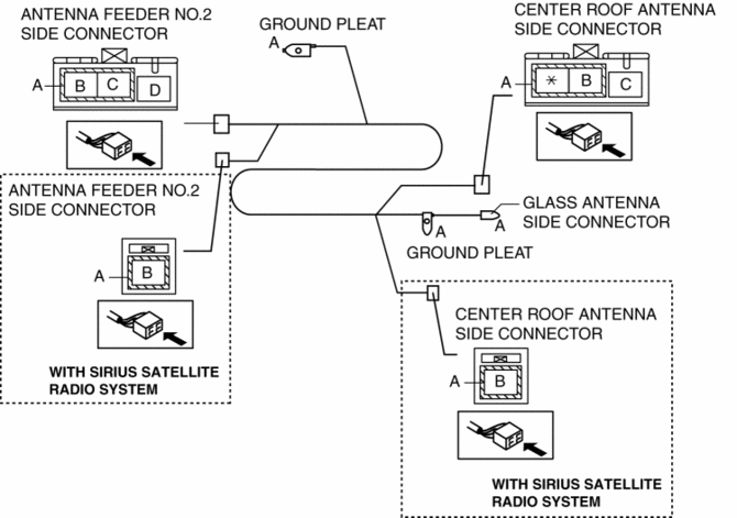
5. Disconnect antenna feeder No.2.
6. Disconnect the roof antenna connector.
7. Disconnect the glass antenna.
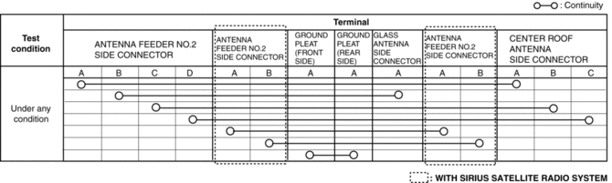
8. Verify that the continuity between antenna feeder No.3 terminals is as indicated in the table.
-
If not as indicated in the table, replace antenna feeder No.3.
 Antenna Feeder No.2 Removal/Installation
Removal
1. Disconnect the negative battery cable..
2. Remove the following parts:
a. Sunroof seaming welt (with sunroof system).
b. A-pillar trim.
c. Front map light.
d. Sunvisor.
e. Fron ...
 Antenna Feeder No.3 Removal/Installation
1. Disconnect the negative battery cable..
2. Remove the following parts:
a. B-pillar lower trim.
b. Front seat belt adjusting cover.
c. Front seat belt upper anchor installation bolt.
d. B- ...
Other materials:
Windshield Wiper Motor Inspection
1. Disconnect the negative battery cable..
2. Remove the following parts:
a. Windshield wiper arm and blade.
b. Cowl grille.
Windshield Wiper Motor Inspection
1. Apply battery positive voltage and connect the ground to the windshield wiper
motor terminals as indicated in the table below a ...
Pressure Sensor Removal/Installation [Two Step Deployment Control System]
WARNING:
Handling the pressure sensor improperly can accidentally operate (deploy)
the air bag module, which may seriously injure you. Read the air bag system
service warnings and cautions before handling the pressure sensor..
1. Switch the ignition to off.
2. Disconnect the ne ...
Blind Spot Monitoring (Bsm) Off Indicator Light
Purpose
The BSM OFF indicator light informs the driver that the Blind Spot Monitoring
(BSM) system is turned off or there is a malfunction in the system.
Function
The instrument cluster illuminates the BSM OFF indicator light based on the
BSM system off signal sent via a CA ...
