Mazda CX-5 Service & Repair Manual: Antenna Feeder No.3 Removal/Installation
1. Disconnect the negative battery cable..
2. Remove the following parts:
a. B-pillar lower trim.
b. Front seat belt adjusting cover.
c. Front seat belt upper anchor installation bolt.
d. B-pillar upper trim.
e. Trunk board.
f. Trunk end trim.
g. Trunk side trim.
h. D-pillar trim.
i. C-pillar trim.
j. Liftgate upper trim (with SIRIUS satellite radio system).
3. Remove the rear passenger's assist handle..
4. Partially peel back the headliner.
NOTE:
-
If the headliner is peeled back excessively, the headliner could become creased. Be careful not to peel back the headliner excessively.
5. Disconnect antenna feeder No.2.
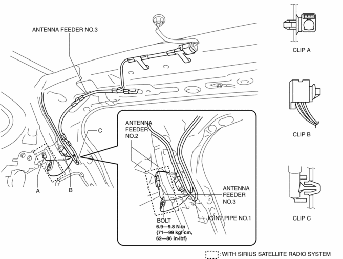
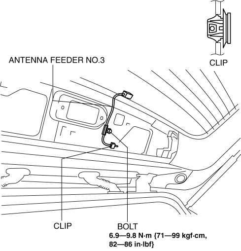
6. Remove the bolt.
7. Remove clips A and B.
8. Remove joint pipe No.1 clip.
9. Remove clips D and E.
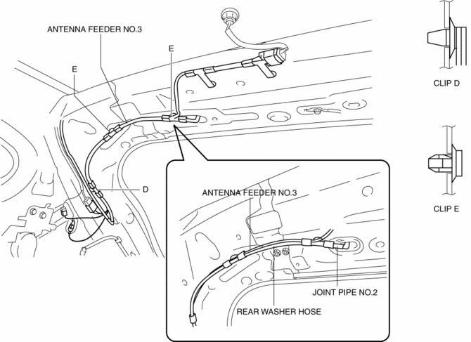
10. Disconnect joint pipe No.2.
11. Remove clips F and G.
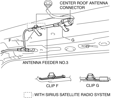
12. Disconnect the center roof antenna.
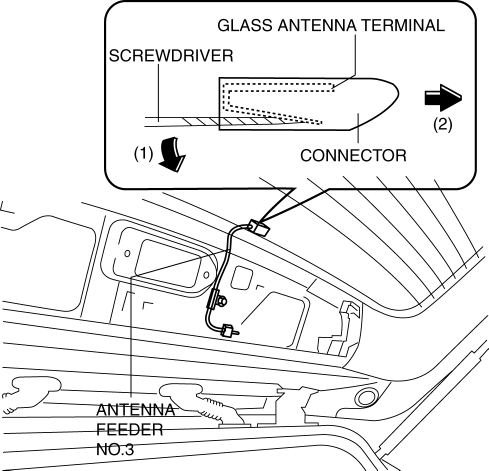
13. Using a screwdriver wrapped in protective tape, pull the connector in the direction of the arrow (2) shown in the figure while pressing glass antenna terminal in the direction of the arrow (1) shown in the figure, and disengage the glass antenna terminal from the connector. (with SIRIUS satellite radio system)
14. Disconnect the connector. (with SIRIUS satellite radio system)
15. Remove the bolt. (with SIRIUS satellite radio system)
16. Remove the clip. (with SIRIUS satellite radio system)
17. Partially peel the liftgate grommet in the direction of arrow (1) shown in the figure, and remove the liftgate grommet from the liftgate grommet inner. (with SIRIUS satellite radio system)
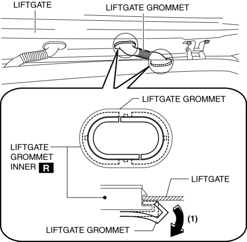
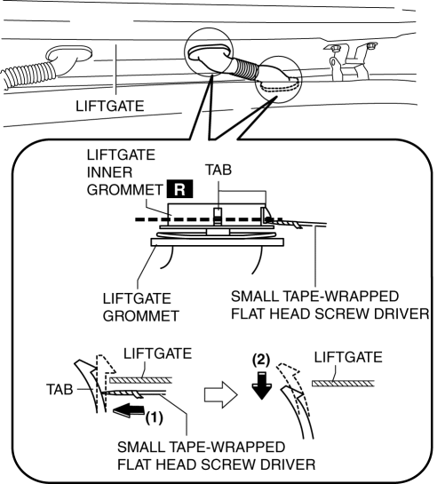
18. Using a screwdriver wrapped in protective tape, pull the liftgate grommet in the direction of the arrow (2) shown in the figure while pressing the liftgate grommet inner tab in the direction of the arrow (1) shown in the figure, and disengage the liftgate from the liftgate grommet. (with SIRIUS satellite radio system)
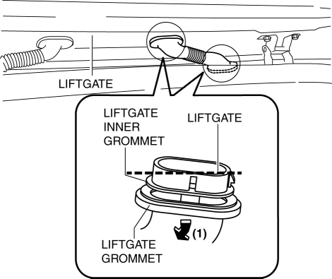
19. Pull the liftgate grommet in the direction of the arrow (1) shown in the figure and remove it.
20. Pull out the disconnected connectors of the liftgate side and vehicle interior side and antenna feeder No.3. (with SIRIUS satellite radio system)
21. Remove antenna feeder No.3.
22. Install in the reverse order of removal.
 Antenna Feeder No.3 Inspection
1. Disconnect the negative battery cable..
2. Remove the following parts:
a. Front scuff plate.
b. Rear scuff plate.
c. B-pillar lower trim.
d. Front seat belt adjusting cover.
e. Front se ...
 Audio Amplifier
Purpose, Function
The audio signal (analog voltage waveform) output from the unit equipped
on the vehicle is converted into a digital pulse. The converted digital pulse
signal is amplifie ...
Other materials:
Rear Differential Disassembly
WARNING:
The engine stand is equipped with a self-lock mechanism, however, if the
rear differential is in a tilted condition, the self-lock mechanism could become
inoperative. If the rear differential unexpectedly rotates it could cause injury,
therefore do not maintain the rear dif ...
Disc Pad (Rear) Replacement
1. Remove in the order indicated in the table.
2. Install in the reverse order of removal.
3. After installation, pump the brake pedal a few times and inspect the following:
The disc pad projection is securely installed to the piston groove
Parking brake lever stroke
Bra ...
Headliner
Purpose/Function
The headliner is equipped with a shock absorbing pad for driver's head protection
during a collision.
Construction
The front and rear side of the headliner is equipped with a shock absorbing
pad with a plastic rib-pad structure.
...
