Mazda CX-5 Service & Repair Manual: Air Bag System Warning Light [Two Step Deployment Control System]
Purpose
-
The air bag system warning light notifies the driver of a malfunction in the SRS air bag system.
Function
-
If a malfunction occurs in the SRS air bag system, the air bag system warning light illuminates or flashes.
Construction
-
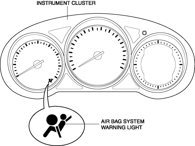
LEDs (light-emitting diode) have been adopted for the air bag system warning light.
-
The air bag system warning light is built into the instrument cluster.
Operation
-
When the ignition is switched ON, the instrument cluster illuminates the air bag system warning light for a specified period to indicate that the SRS air bag system is performing initialization diagnostics. If there is no malfunction in the SRS air bag system, the indicator light turns off.
-
If the SAS control module detects a malfunction in the SRS air bag system, it sends a warning signal to the instrument cluster via CAN communication. The instrument cluster illuminates or flashes the air bag system warning light based on the warning signal it receives to display the DTC.
-
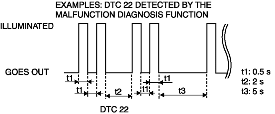
If there is a malfunction in the SRS air bag system, the air bag system warning light displays DTCs according to the following patterns:
-
If there are several malfunctions in the SRS air bag system, the DTC of the highest priority ranking is displayed first.
Fail-safe
-
Function not equipped.
 Air Bag System Warning Light [Standard Deployment Control System]
Purpose
The air bag system warning light notifies the driver of a malfunction in
the SRS air bag system.
Function
If a malfunction occurs in the SRS air bag system, the air bag ...
 Automatic Transaxle Warning Light [Fw6 A EL, Fw6 Ax EL]
Purpose/Function
The automatic transaxle warning light illuminates when the transaxle has
malfunction.
Construction
The automatic transaxle warning light is built into the instr ...
Other materials:
Main Relay [Skyactiv G 2.0]
Purpose/Function
Supplies power to each part.
Supplies battery voltage to each part based on the signals from the PCM even
though the ignition is switched on or off.
Construction
Installed to the relay and fuse block.
Operation
After the contact poin ...
Ambient Temperature Sensor [Full Auto Air Conditioner]
Purpose
The ambient temperature sensor detects the ambient temperature.
Function
The ambient temperature sensor converts the detected temperature to an electric
signal.
Construction
A thermistor-type ambient temperature sensor has been adopted.
The ambient ...
Trip Computer Information System
Outline
The trip computer system displays the instantaneous fuel economy, average
fuel economy, remaining distance to empty, and the average vehicle speed.
The instrument cluster performs trip computer system fail-safe..
Function
The instrument cluster controls the tri ...
