Mazda CX-5 Service & Repair Manual: Turn Signal/Hazard Warning Indicator Lights
Purpose
-
Notifies the driver that a turn light, the hazard warning lights are flashing.
Function
-
Flashes according to the turn switch and hazard warning switch operations.
Construction
-
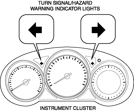
Displayed in the instrument cluster.
Operation
Turn system
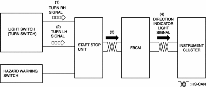
1. When the turn switch is operated to the RH position, a turn RH signal is input to the start stop unit.
2. When the turn switch is operated to the LH position, a turn LH signal is input to the start stop unit.
3. The start stop unit sends the turn RH or LH signal to the front body control module (FBCM).
4. The front body control module (FBCM) sends the turn RH or LH signal to the instrument cluster as a direction indicator light signal.
5. When a direction indicator light signal is received, the instrument cluster flashes the direction indicator light.
Hazard system
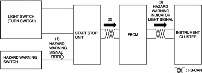
1. When the hazard switch is turned on, a hazard signal is input to the start stop unit.
2. The start stop unit sends a hazard signal to the front body control module (FBCM).
3. The front body control module (FBCM) sends the hazard signal to the instrument cluster as a hazard warning flashing signal.
4. When the hazard warning flash signal is received, the instrument cluster flashes the hazard warning lights.
Fail-safe
-
Function not equipped.
 Turn And Hazard Indicator Alarm
Purpose
The turn and hazard indicator alarm notifies the driver that a turn light
or the hazard warning lights are flashing.
Function
When the instrument cluster receives the tu ...

Other materials:
Bumper Slider Removal/Installation
Front Bumper Slider
1. Disconnect the negative battery cable..
2. Remove the seal board upper..
3. Remove the front bumper..
4. Remove bolts A.
5. Pull the front bumper slider in the direction of the arrow while detaching
pins B and hook C.
6. Install in the reverse order of removal ...
Recliner Motor Inspection
WARNING:
Handling a side air bag improperly can accidentally operate (deploy) the
air bag, which may seriously injure you. Read the service warnings/cautions
in the Workshop Manual before handling the front seat (side air bag integrated)..
1. Disconnect the negative battery cable ...
Crankshaft Pulley
Purpose, Function
The crankshaft pulley transmits the drive force to the auxiliary parts via
the drive belt.
The crankshaft pulley suppresses torsional vibration of the crankshaft.
Construction
The crankshaft pulley is installed to the front of the crankshaft.
...
