Mazda CX-5 Service & Repair Manual: Torque Converter Clutch (TCC) Control [Fw6 A EL, Fw6 Ax EL]
Outline
-
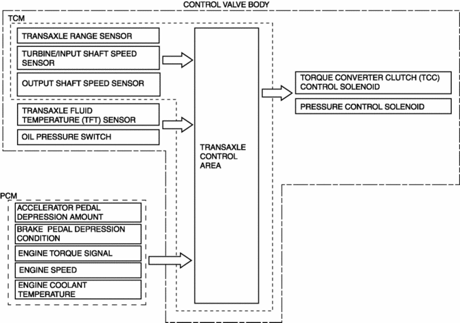
For TCC control, a newly developed, full range TCC control has been adopted. The TCC range has been significantly widened by having the smoothness unique to the torque converter during acceleration from a stop take precedence and actively controlling TCC directly after acceleration from a stop. Therefore, a contribution to low fuel consumption and vehicle operability with a direct feel have been achieved.
-
Lower fuel consumption and improved emission performance have been achieved by performing the TCC control during deceleration with the accelerator pedal fully closed and by fuel-cut during TCC.
Construction

-
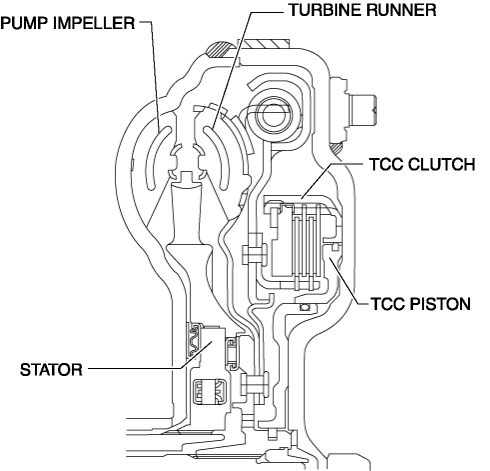
The TCC mechanism consists of a torque converter clutch, TCC piston, and a damper which are installed inside the torque converter.
-
A multi-plate type torque converter clutch has been adopted for improved durability. Also, by reducing the size of the clutch diameter, improved handling is achieved by the ability to respond to the precise control by the full range TCC.
-
Vibration during TCC engagement is suppressed by the improved damper performance.

Operation
-
TCC engagement
-
A current signal is sent from the TCM to the TCC control solenoid during TCC engagement. At the same time, the TCC piston engagement pressure is gradually increased.
-
As a result, the TCC piston is pressure-bonded to the TCC clutch slowly to perform smooth TCC engagement.
-
TCC release
-
A current signal is sent from the TCM to the TCC control solenoid during TCC release. At the same time, the TCC piston engagement pressure is gradually drained.
-
As a result, the TCC piston releases the TCC clutch slowly to release the TCC smoothly.
-
Inhibition of TCC control
-
If any one of the following conditions is met, the torque converter clutch control is inhibited.
-
TCC solenoid malfunction
-
ATF temperature is specification or less
-
Engine speed signal is specification or less
-
Turbine shaft speed is specification or less
-
Other than D/M position
 Torque Converter Clutch (TCC) Control Solenoid [Fw6 A EL, Fw6 Ax EL]
Purpose/Function
The torque converter clutch (TCC) control solenoid adjusts the hydraulic
pressure in the TCC control circuit based on the current demand from the TCM
according to the veh ...
 Torque Converter [Fw6 A EL, Fw6 Ax EL]
Purpose/Function
By use of an optimized torus shape (wing) matching the output characteristics
of the engine, the torque converter achieves efficient force transmission and
reduced fuel c ...
Other materials:
Seat Warmer Control Unit Removal/Installation
WARNING:
Handling a side air bag improperly can accidentally operate (deploy) the
air bag, which may seriously injure you. Read the service warnings/cautions
in the Workshop Manual before handling the front seat (side air bag integrated)..
1. Switch the ignition off (LOCK).
2. ...
Corner Plate Installation [Panel Replacement]
Symbol Mark
Installation Procedure
1. When installing new parts, measure and adjust the body as necessary to conform
with standard dimensions.
2. Drill holes for the plug welding before installing the new parts.
3. After temporarily installing new parts, make sure the related parts fit p ...
Front Seat
Purpose, Function
The front seats are structured to reduce impact force applied to the head
of the occupant in a vehicle collision.
8WAY or 6WAY power seats have been adopted on the driver's seat. (with power
seat system).
A seat warmer system has been adopted on the ...
