Mazda CX-5 Service & Repair Manual: PCM Removal/Installation
CAUTION:
-
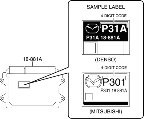
There are two types of PCM settings. If the incorrect PCM is installed, it could cause interference with engine control.
-
When replacing the PCM, verify the first four digits of the part number indicated on the PCM label before replacement, and replace the PCM with one having the same part number.
1. Disconnect the negative battery cable..
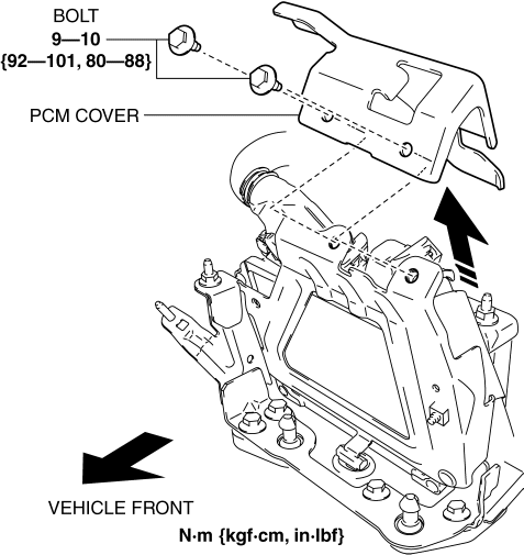
2. Remove the PCM cover..
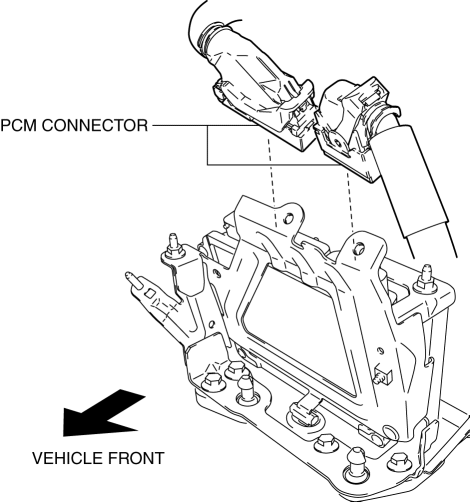
3. Disconnect the PCM connector..
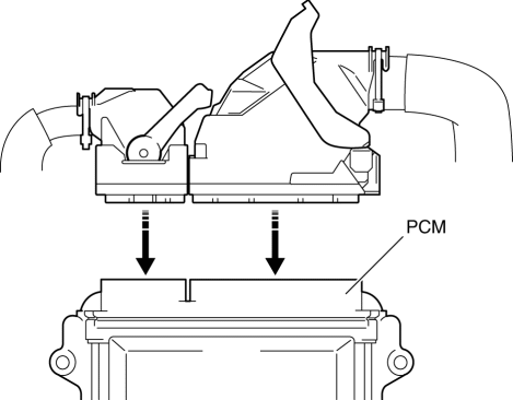
4. Remove the PCM assembly from the battery tray.
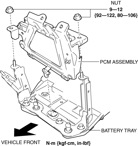
5. Remove the PCM from the PCM bracket.
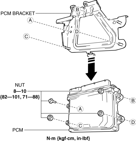
6. Install in the reverse order of removal.
7. When replacing the PCM on the vehicles, perform the following:
-
PCM configuration.
NOTE:
-
If configuration cannot be performed by reading/writing of the vehicle specification information, perform the configuration using As-Built information after replacing the PCM..
-
-
Immobilizer system-related parts programming.
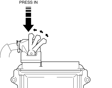
PCM Cover Installation Note
1. Insert the PCM cover end into area A shown in the figure.
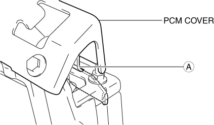
2. Temporarily tighten the two bolts, then completely tighten them.
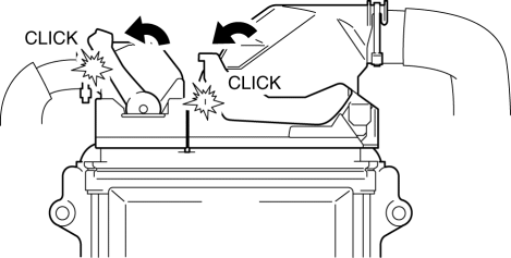
PCM Connector Connection Note
CAUTION:
-
Do not touch the PCM connector terminal. The terminal is extremely thin and can be damaged by touching it.
-
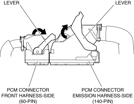
If the PCM connector is inserted at an angle and the lever is moved, the connector could be damaged. Verify that the PCM connector is inserted straight.
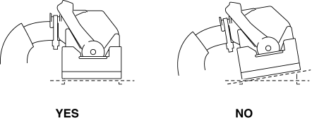
1. Set the PCM connector to the position shown in the figure.
2. Align the PCM connector straight against the connection surface.
3. Insert the PCM connector straight and press it in until the lever moves up naturally. (Front harness-side connector)
4. Press the PCM connector lever until a click sound is heard.
 PCM Inspection
Without Using the M-MDS
NOTE:
Because the PCM uses a waterproof connector, the inspection for the voltage/wave
pattern cannot be performed. The following values are for reference.
Te ...
 PCM
PCM
Purpose/Function
High-level driveability and lower fuel consumption have been realized by
controlling the appropriate engine conditions (fuel injection/ignition timing)
according to opera ...
Other materials:
Moonroof
The moonroof can be opened or closed electrically only when the ignition is switched
ON.
WARNING
Do not let passengers stand up or extend part of the body through the open moonroof
while the vehicle is moving:
Extending the head, arms, or other parts of the body through the moonroof is
da ...
Charcoal Canister Removal/Installation
U.S.A. And CANADA
1. Disconnect the negative battery cable..
2. Remove the floor under cover..
3. Remove in the order indicated in the table.
1
Quick release connector
(See QUICK RELEASE CONNECTOR (EMISSION SYSTEM) REMOVAL/INSTALLATION [SKYACTIV-G
2.0].)
...
Back Up Light Switch Removal/Installation [C66 M R]
1. Disconnect the negative battery cable..
2. Remove the front under cover No.2..
3. Remove in the order indicated in the table.
4. Install in the reverse order of removal.
1
Back-up light switch connector
2
Back-up light switch
...
