Mazda CX-5 Service & Repair Manual: Headlight Bulb Removal/Installation
Halogen Type
Headlight LO bulb
1. Disconnect the negative battery cable..
2. Disconnect the connector.
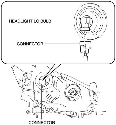
3. Rotate the headlight LO bulb in the direction of the arrow (1) shown in the figure to remove it in the direction of the arrow (2) shown in the figure.
CAUTION:
-
A halogen bulb generates extremely high heat when it is illuminated. If the surface of the bulb is soiled, excessive heat will build up and the life of the bulb will be shortened. When replacing the bulb, hold the metal flange, not the glass.
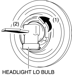
4. Install in the reverse order of removal.
Headlight HI bulb
1. Disconnect the negative battery cable..
2. Disconnect the connector.
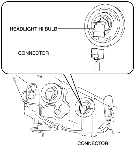
3. Rotate the headlight HI bulb in the direction of the arrow (1) shown in the figure and remove it in the direction of the arrow (2) shown in the figure.
CAUTION:
-
A halogen bulb generates extremely high heat when it is illuminated. If the surface of the bulb is soiled, excessive heat will build up and the life of the bulb will be shortened. When replacing the bulb, hold the metal flange, not the glass.
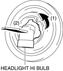
4. Install in the reverse order of removal.
Discharge Type
WARNING:
-
Incorrect servicing of the discharge headlights could result in electrical shock. Before servicing the discharge headlights, always refer to the service warnings..
Headlight HI/LO bulb (LH)
1. Disconnect the negative battery cable..
2. Remove the air cleaner cover..
3. Remove the relay and fuse block upper cover..
4. Remove the nut and screw.
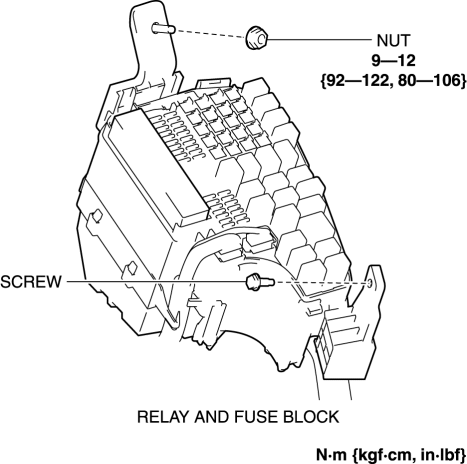
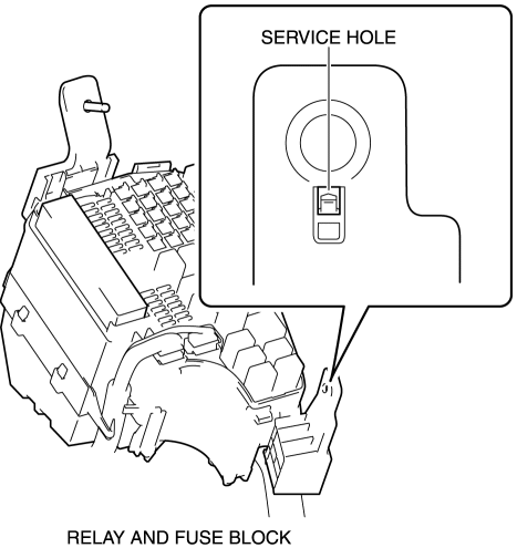
5. Insert a tape-wrapped flathead screwdriver into the service hole in the position shown in the figure.
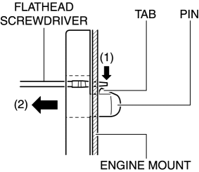
6. While pressing the pin tab in the direction of the arrow (1) shown in the figure using a flathead screwdriver, pull the pin in the direction of the arrow (2) shown in the figure to detach the pin tab and engine mount.
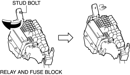
7. Pull out the relay and fuse block from the stud bolt and set it aside as shown in the figure.
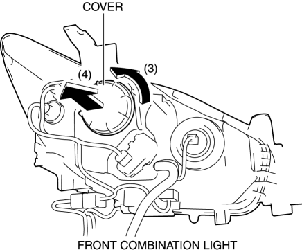
8. Rotate the cover in the direction of the arrow (3) shown in the figure and remove it from the front combination light in the direction of the arrow (4) shown in the figure.
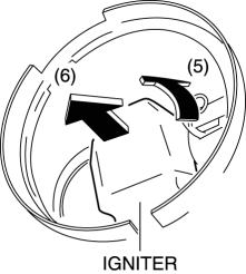
9. Rotate the igniter in the direction of the arrow (5) shown in the figure and remove it from the front combination light in the direction of the arrow (6) shown in the figure.
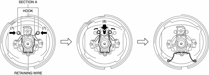
10. Move section A of the bulb retaining wire in the direction of the arrow (7) shown in the figure, pull it in the direction of the arrow (8) shown in the figure, and detach the bulb retaining wire and hook.
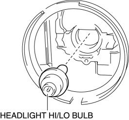
11. Remove the headlight HI/LO bulb.
CAUTION:
-
The discharge headlight bulb generates extremely high heat when it is illuminated. If the surface of the bulb is soiled, excessive heat will build up and the life of the bulb will be shortened. When replacing the bulb, hold the metal flange, not the glass.
12. Install in the reverse order of removal.
Headlight HI/LO bulb (RH)
1. Disconnect the negative battery cable..
2. Remove the washer tank bracket..
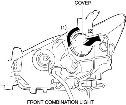
3. Rotate the cover in the direction of the arrow (1) shown in the figure and remove it from the front combination light in the direction of the arrow (2) shown in the figure.
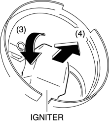
4. Rotate the igniter in the direction of the arrow (3) shown in the figure and remove it from the front combination light in the direction of the arrow (4) shown in the figure.
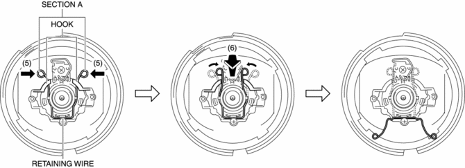
5. Move section A of the bulb retaining wire in the direction of the arrow (5) shown in the figure, pull it in the direction of the arrow (6) shown in the figure, and detach the bulb retaining wire and hook.
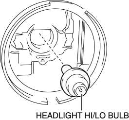
6. Remove the headlight HI/LO bulb.
CAUTION:
-
The discharge headlight bulb generates extremely high heat when it is illuminated. If the surface of the bulb is soiled, excessive heat will build up and the life of the bulb will be shortened. When replacing the bulb, hold the metal flange, not the glass.
7. Install in the reverse order of removal.
 Headlight Auto Leveling System Initialization
NOTE:
The AFS control module records the vehicle height while it is unoccupied
by performing the headlight auto leveling system initial setting.
Perform headlight auto leveling syst ...
 Headlight High Beam Indicator Light
Purpose
Notifies the user that the headlights (HI) are illuminated.
Function
Illuminates when the headlight (HI) or parking illumination conditions are
met.
Construction
...
Other materials:
Crankshaft Position (CKP) Sensor Removal/Installation
CAUTION:
When foreign material such as an iron chip is on the CKP sensor, it can cause
abnormal output from the sensor because of flux turbulence and adversely affect
the engine control. Be sure there is no foreign material on the CKP sensor when
replacing.
Do not assemble t ...
Manual Transaxle Removal/Installation [C66 M R]
Removal
1. Disconnect the negative battery cable..
2. Remove the plug hole plate..
3. Remove the front under cover No.2..
4. Remove the front under cover No.1..
5. Remove the splash shield..
6. Drain the manual transaxle oil..
7. Disconnect and/or remove the following parts in the engin ...
Fuel Gauge Sender Unit Inspection [2 Wd]
NOTE:
For the fuel gauge sender unit removal/installation, refer to the fuel pump
removal/installation because the fuel gauge sender unit is integrated with the
fuel pump..
1. Verify that the resistance at fuel gauge sender unit terminals D and C is
as indicated in the table ac ...
