Mazda CX-5 Service & Repair Manual: General Procedures (Suspension)
Wheel and Tire Installation
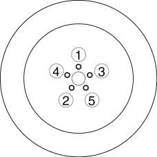
1. When installing the wheels and tires, tighten the wheel nuts in a criss-cross pattern to the following tightening torque.

-
Tightening torque
-
108—147 N·m {12—14 kgf·m, 80—108 ft·lbf}
Suspension Links Removal/Installation
1. For the joint sections with rubber bushings, raise the vehicle using a lift, and then temporarily tighten the installation bolts and nuts. Lower the vehicle to the ground and tighten them to the specified tightening torque.
Connector Disconnection
1. Disconnect the negative battery cable before performing any work that requires handling of connectors..
Headlight Auto Leveling System Initialization (Vehicle with discharge headlight system)
1. Initialize the auto leveling sensor, when performing the following services..
-
Removing the auto leveling sensor
-
Disconnecting the auto leveling sensor link
-
Removing the suspension parts related the vehicle height
 General
...
 Rear Trailing Link Removal/Installation
1. Remove the floor under cover..
2. Disconnect the rear parking cable..
3. Remove in the order indicated in the table.
4. Install in the reverse order of removal.
5. Inspect the wheel a ...
Other materials:
Liftgate
WARNING
Never allow a person to ride in the luggage compartment:
Allowing a person to ride in the luggage compartment is dangerous.
The person in the luggage compartment could be seriously injured or killed during
sudden braking or a collision.
Do not drive with the liftgate open:
Exhaust gas ...
Intake Air Temperature (Iat) Sensor Inspection
IAT Sensor No.1
Resistance inspection
NOTE:
Because the IAT sensor No.1 is integrated in the MAF sensor, replacing the
IAT sensor No.1 includes replacement of the MAF sensor/IAT sensor No.1.
1. Disconnect the negative battery cable..
2. Disconnect the MAF sensor/IAT sensor No.1 ...
Quarter Window Glass Removal
1. Disconnect the negative battery cable..
2. Remove the following parts:
a. Trunk board.
b. Trunk end trim.
c. Rear scuff plate.
d. Trunk side trim.
e. D-pillar trim.
f. C-pillar trim.
3. Apply protective tape along the edge of the body and the quarter window glass.
WARNING: ...
