Mazda CX-5 Service & Repair Manual: Front Seat Back Trim Removal/Installation
WARNING:
-
Handling a side air bag improperly can accidentally operate (deploy) the air bag, which may seriously injure you. Read the service warnings/cautions in the Workshop Manual before handling the front seat (side air bag integrated)..
-
If the sliding mechanisms on both sides are not locked after assembling the front seat, the front seat will operate accidentally while the vehicle is driven, which could result in serious injury. After assembling the front seat, shake it up and down and verify that the sliding mechanism on the both sides are locked.
CAUTION:
-
If the slide bar is operated after the front seat is removed, the left/right slide positions will deviate and the adjuster unit could be damaged after the front seat is installed. After removing a front seat, do not operate the slider lever.
-
Verify that there are no malfunctions in the forward/back slide of the seat and in the adjuster unit after installing a front seat.
-
When performing the procedure with a front seat removed from the vehicle, perform the procedure on a clean cloth so as not to damage or soil the seat.
-
When the passenger's seat is removed, perform the seat weight sensor inspection using the M-MDS after installing the passenger's seat..
-
When the passenger's seat is replaced with a new one, perform the seat weight sensor calibration using the M-MDS..
Driver-side (with power seat system)
1. Switch the ignition off (LOCK).
2. Disconnect the negative battery cable and wait for 1 min
..
3. Remove the headrest.
4. Remove the front seat..
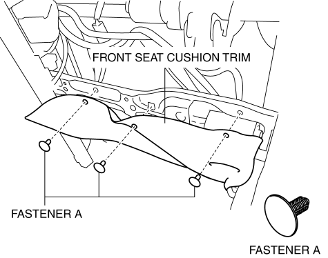
5. Remove fasteners A and set the front seat cushion trim aside.
6. Disconnect the side air bag module connector.
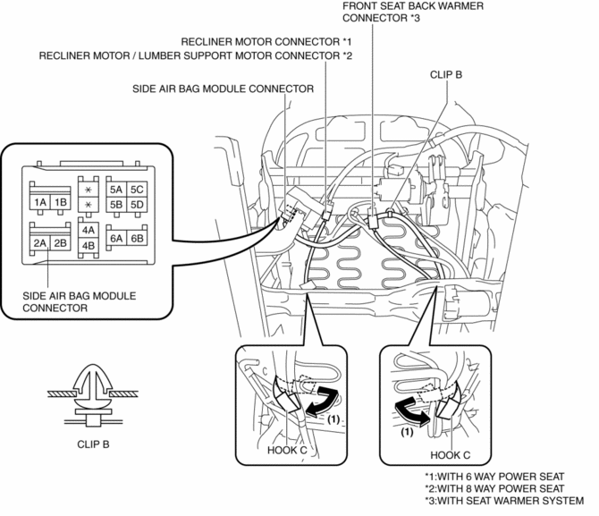
7. Disengage clip B.
8. Disconnect the front seat back warmer connector. (with seat warmer system)
9. Disconnect the recliner motor connector. (with 6 way power seat)
10. Disconnect the recliner motor/lumber support motor connector. (with 8 way power seat)
11. Set hooks C aside in the direction of the arrow (1) shown in the figure.
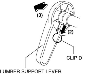
12. Remove the clip D in the direction of the arrow (2) shown in the figure and remove the lumber support lever in the direction of the arrow (3). (with 6 way power seat)
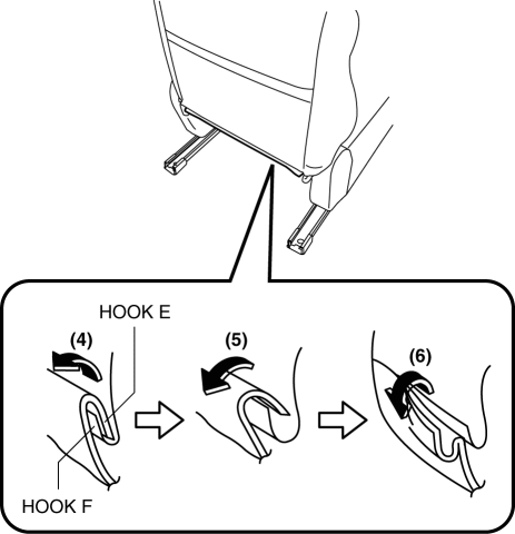
13. Slide hook E in the order of arrows (4), (5), (6) shown in the figure and disconnect them from hook F.
14. Open fasteners G.
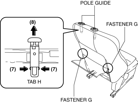
15. Partially peel back the seat back trim, release tabs H in the direction of the arrow (7) shown in the figure and pull out the pole guide in the direction of the arrow (8).
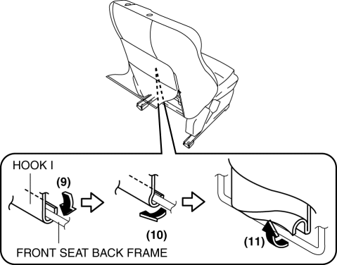
16. Partially peel back the front seat back trim and slide hook I in the order of the arrows (9), (10), and (11) shown in the figure, and remove it from the front seat back frame.
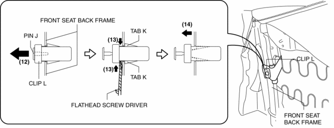
17. Pull out pin J in the direction of the arrow (12) shown in the figure, and using a flathead screwdriver wrapped in protective tape, release the tabs K in the direction of the arrow (13) shown in the figure while removing the clip L in the direction of the arrow (14).
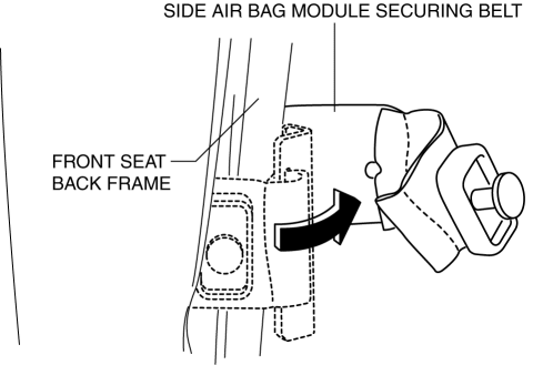
18. Remove the side air bag module securing belt from the front seat back frame.
19. Pull the side air bag module wiring harness in the direction of the arrow (15) shown in the figure, and pull it out through the hole in the front seat back pad.
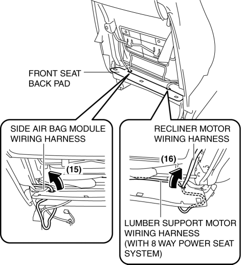
20. Pull the recliner motor wiring harness and lumber support wiring harness in the direction of the arrow (16) shown in the figure, and pull it out through the hole in the front seat back pad. (with 8 way power seat)
21. Pull the recliner motor wiring harness in the direction of the arrow (16) shown in the figure, and pull it out through the hole in the seat back pad. (with 6 way power seat)
22. Pull out the front seat back pad and front seat back trim, and the front seat back warmer connector harness towards the front of the front seat.
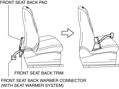
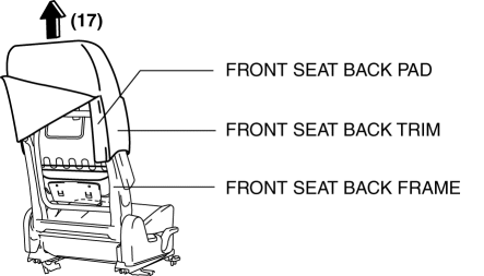
23. Lift up the front seat back trim and front seat back pad in the direction of the arrow (17) as a single unit and remove it from the front seat back frame.
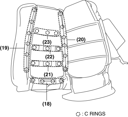
24. Remove the C rings in the order of (18), (19), (20), (21), (22), and (23), shown in the figure, and remove the front seat back trim from the front seat back pad.
CAUTION:
-
If a damaged C rings are reused, it may not be possible to install the front seat back trim and front seat back pad correctly. When removing and installing C rings, be careful not to damage them.
-
If the C rings are damaged, replace the C rings with a new one.
25. Install in the reverse order of removal.
Driver-side (without power seat system)
1. Switch the ignition off (LOCK).
2. Disconnect the negative battery cable and wait for 1 min
..
3. Remove the headrest.
4. Remove the front seat..
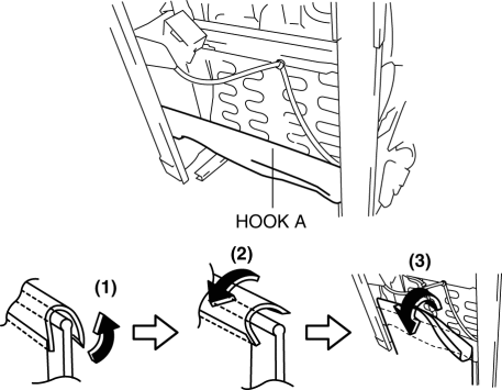
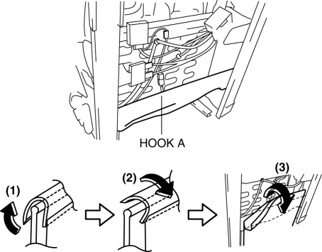
5. Slide hook A in the order of arrows (1), (2), (3) shown in the figure and set the front seat cushion trim aside.
6. Disconnect the side air bag module connector.
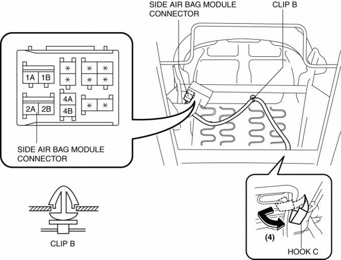
7. Disengage clip B.
8. Set hook C aside in the direction of the arrow (4) shown in the figure.
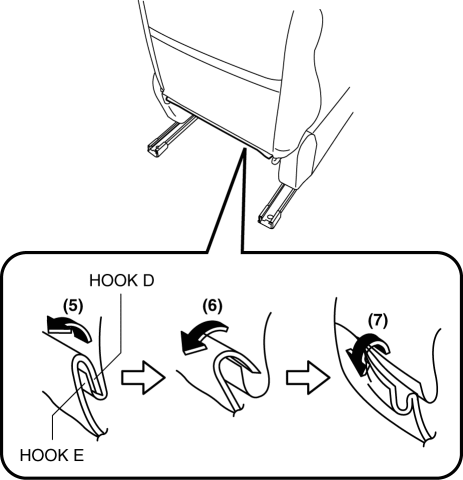
9. Slide hook D in the order of arrows (5), (6), (7) shown in the figure and disconnect them from hook E.
10. Open fasteners F.
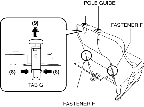
11. Partially peel back the seat back trim, release tab G in the direction of the arrow (8) shown in the figure and pull out the pole guide in the direction of the arrow (9).
12. Partially peel back the front seat back trim and slide hook H in the order of the arrows (10), (11), and (12) shown in the figure, and remove it from the front seat back frame.
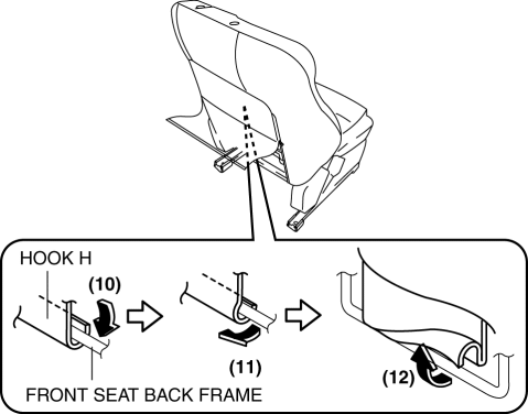
13. Pull out pin I in the direction of the arrow (13) shown in the figure, and using a flathead screwdriver wrapped in protective tape, release the tabs J in the direction of the arrow (14) shown in the figure while removing the clip K in the direction of the arrow (15).
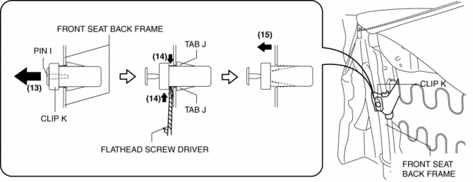
14. Remove the side air bag module securing belt from the front seat back frame.

15. Pull the side air bag module wiring harness in the direction of the arrow (16) shown in the figure, and pull it out through the hole in the front seat back pad.
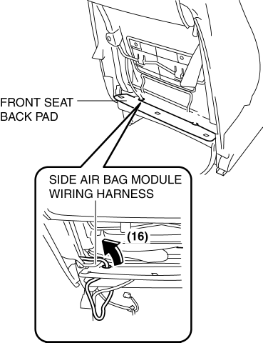
16. Pull out the front seat back pad and front seat back trim towards the front of the front seat.
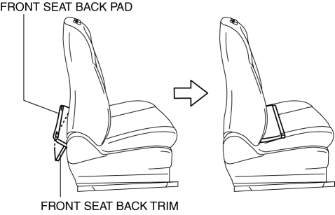
17. Lift up the front seat back trim and front seat back pad in the direction of the arrow (17) as a single unit and remove it from the front seat back frame.
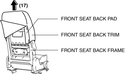
18. Remove the C rings in the order of (18), (19), (20), and (21) shown in the figure, and remove the front seat back trim from the front seat back pad.
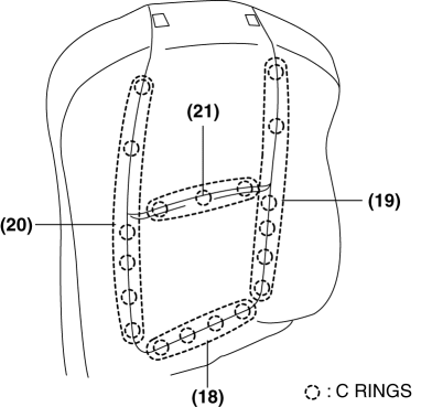
CAUTION:
-
If a damaged C rings are reused, it may not be possible to install the front seat back trim and front seat back pad correctly. When removing and installing C rings, be careful not to damage them.
-
If a C rings are damaged, replace the C rings with a new one.
19. Install in the reverse order of removal.
Passenger-side
1. Switch the ignition off (LOCK).
2. Disconnect the negative battery cable and wait for 1 min
..
3. Remove the headrest.
4. Remove the front seat..
5. Slide hooks A in the order of arrows (1), (2), (3) shown in the figure and set the front seat cushion trim aside.
6. Disconnect the side air bag module connector.
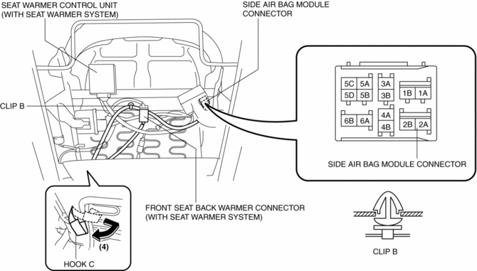
7. Disconnect the front seat back warmer connector. (With seat warmer system)
8. Disengage clip B.
9. Set hook C aside in the direction of the arrow (4) shown in the figure.
10. Slide hook D in the order of arrows (5), (6), (7) shown in the figure and disconnect them from hook E.
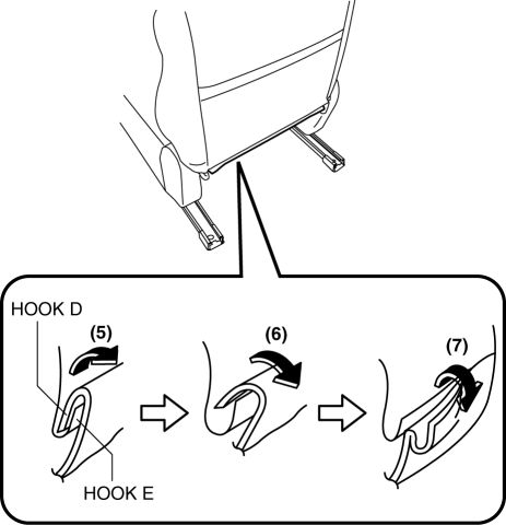
11. Open fasteners F.
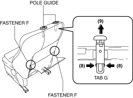
12. Partially peel back the seat back trim, release tabs G in the direction of the arrow (8) shown in the figure and pull out the pole guide in the direction of the arrow (9).
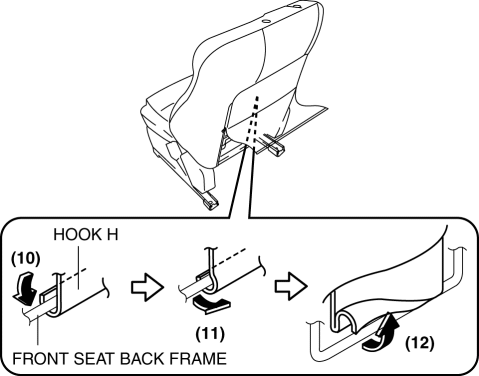
13. Partially peel back the front seat back trim and slide hook H in the order of the arrows (10), (11), and (12) shown in the figure, and remove it from the front seat back frame.
14. Pull out pin I in the direction of the arrow (13) shown in the figure, and using a flathead screwdriver wrapped in protective tape, release the tabs J in the direction of the arrow (14) shown in the figure while removing the clip K in the direction of the arrow (15).
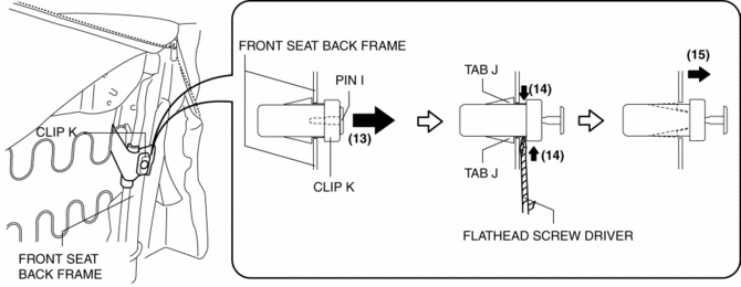
15. Remove the side air bag module securing belt from the front seat back frame.
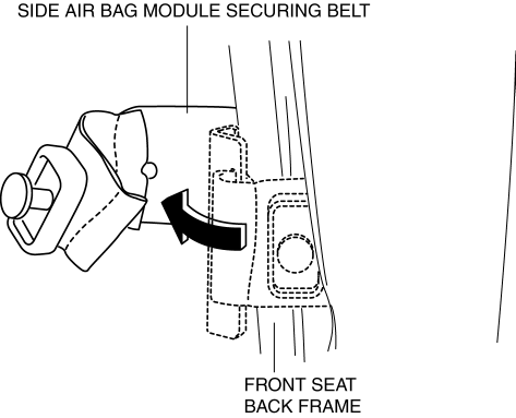
16. Pull the side air bag module wiring harness in the direction of the arrow (16) shown in the figure, and pull it out through the hole in the front seat back pad.
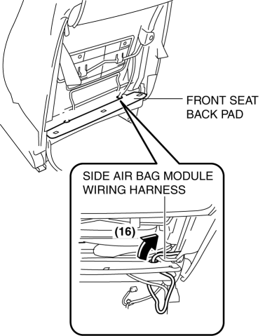
17. Pull out the front seat back pad and front seat back trim, and the front seat back warmer connector towards the front of the front seat.
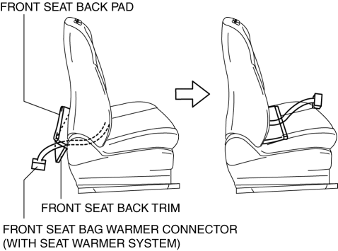
18. Lift up the front seat back trim and front seat back pad in the direction of the arrow (17) as a single unit and remove it from the front seat back frame.

19. Remove the C rings in the order of (18), (19), (20), (21), (22) and (23), shown in the figure, and remove the front seat back trim from the front seat back pad. (With power seat system for driver-side)

CAUTION:
-
If a damaged C rings are reused, it may not be possible to install the front seat back trim and front seat back pad correctly. When removing and installing C rings, be careful not to damage them.
-
If the C rings are damaged, replace the C rings with a new one.
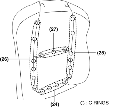
20. Remove the C rings in the order of (24), (25), (26), and (27) shown in the figure, and remove the front seat back trim from the front seat back pad. (Without power seat system for driver-side)
CAUTION:
-
If a damaged C rings are reused, it may not be possible to install the front seat back trim and front seat back pad correctly. When removing and installing C rings, be careful not to damage them.
-
If a C rings are damaged, replace the C rings with a new one.
21. Install in the reverse order of removal.
 Front Seat Back Component Removal/Installation
WARNING:
Handling a side air bag improperly can accidentally operate (deploy) the
air bag, which may seriously injure you. Read the service warnings/cautions
in the Workshop Manual befor ...
 Front Seat Cushion Frame Removal/Installation
WARNING:
Handling a side air bag improperly can accidentally operate (deploy) the
air bag, which may seriously injure you. Read the service warnings/cautions
in the Workshop Manual befor ...
Other materials:
Warranties for Your Mazda
• New Vehicle Limited Warranty
• Powertrain Limited Warranty
• Safety Restraint System Limited Warranty
• Anti-perforation Limited Warranty
• Federal Emission Control Warranty/California
Emission Control Warranty
• Emission Defect Warranty
• Emission Performance Warranty
• E ...
Blind Spot Monitoring (BSM) System
Blind Spot Monitoring (BSM) System
The Blind Spot Monitoring (BSM) system is designed to assist the driver by monitoring
blind spots on both sides of the vehicle to the rear in certain situations such
as when changing lanes on roads and freeways.
The BSM system monitors the detection areas on ...
Front Drive Shaft (Double Offset Joint) Disassembly/Assembly
1. Disassemble in the order indicated in the table.
2. Assemble in the reverse order of disassembly.
1
Boot band (transaxle side)
(See FRONT DRIVE SHAFT (TRIPOD JOINT) DISASSEMBLY/ASSEMBLY.)
2
Clip
(See Clip Disassembly Note.)
...
