Mazda CX-5 Service & Repair Manual: Front Outer Handle Removal/Installation
1. Perform the front door glass preparation..
2. Disconnect the negative battery cable..
3. Remove the following parts:
a. Inner garnish.
b. Front door trim.
c. Front door glass.
d. Front door module panel.
e. Front door key cylinder.
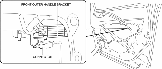
4. Disconnect the keyless antenna connector (With advanced keyless entry system).
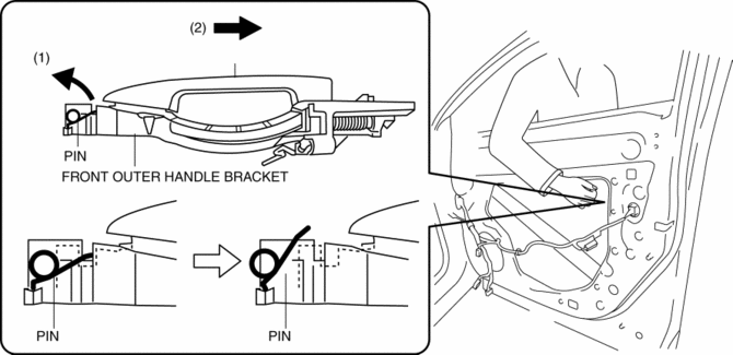
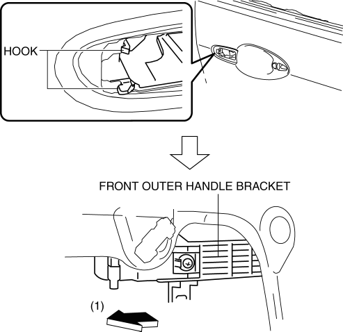
5. While pulling the front outer handle bracket pin in the direction of arrow (1) shown in the figure, pull the front outer handle in the direction of arrow (2) to detach the front outer handle bracket pin and the front outer handle.
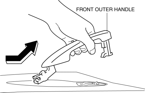
6. Remove the front outer handle in the direction of the arrow shown in the figure.
7. Loosen the screw securing the front outer handle bracket.
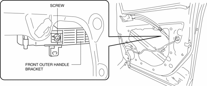
NOTE:
-
The screw cannot be removed because the front outer handle bracket has a stopper which prevents the screw from falling.
8. Pull the front outer handle bracket in the direction of arrow (1) shown in the figure and detach the front outer handle bracket hooks from the body.
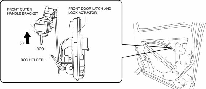
9. Lift the front outer handle bracket in the direction of arrow (2) shown in the figure to pull the rod out of the rod holder..
10. Remove the front outer handle bracket.
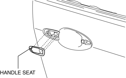
11. Remove the handle seat from the body.
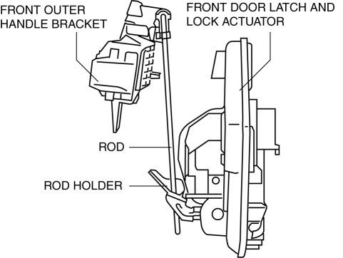
12. Install in the reverse order of removal.
Front Outer Handle Bracket Installation Note
-
To assure that the rod is inserted into the rod holder hole, verify that the there is no excessive play.
 Front Door Removal/Installation
WARNING:
Removing the front door without supporting it could cause the front door
to fall and cause serious injury. Always perform the procedure with at least
one other person to prevent ...
 Hood
Hood
Purpose/Function
The hood is constructed with a large space between the front end of the hood
and the engine to absorb an impact.
Construction
The hood stiffener positioned at t ...
Other materials:
Reduction Gear
Purpose/ Function
The reduction gear transmits the rotation input from the EPS motor, decreasing
the rotation speed and increasing the torque simultaneously.
Construction
The reduction gear consists of the worm wheel located on the steering column
main shaft and the worm sh ...
Front Seat Side Cover Removal/Installation
WARNING:
Handling a side air bag improperly can accidentally operate (deploy) the
air bag, which may seriously injure you. Read the service warnings in the Workshop
Manual before handling the front seat (side air bag integrated)..
If the sliding mechanisms on both sides are ...
Awd Control Module Inspection
NOTE:
AWD CM terminal voltage can vary depending on measuring conditions and vehicle
aging, resulting in misdiagnosis. Therefore, it is necessary to perform an overall
inspection of the input/output systems and AWD CM to determine which part is
malfunctioning.
With the AWD C ...
