Mazda CX-5 Service & Repair Manual: Front Fog Light Aiming
NOTE:
-
Perform front fog light aiming if any of the following work is performed.
-
Front fog light replacement
-
Work that can affect vehicle height such as suspension replacement or removal/installation.
1. Empty the vehicle by having all occupants leave the vehicle and remove all the cargo except for the spare tire, jack and tools equipped on the vehicle.
2. Adjust the air pressure of each tire to the specified value..
3. Move the vehicle to level ground.
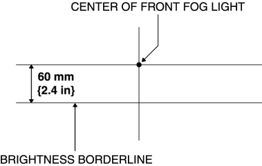
4. Make a screen shown in the figure using double-weight, white paper. (Common for right and left)
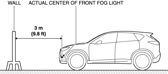
5. Line up the vehicle with the wall so that the distance to the front fog lights is 3 m {9.8 ft}
from the wall.
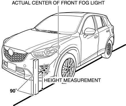
6. Measure the height at the center point of the front fog light.
NOTE:
-
Measure the height at the center point of the front fog light in which the aiming is being adjusted because the vehicle height differs depending on vehicle conditions.
7. Align the center point of the front fog light with the center of the screen.
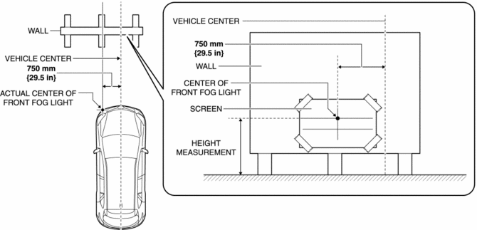
8. Set a partition in front of the front fog light which is not being adjusted to block the light.
9. Start the engine and charge the battery.
10. Turn on the front fog lights.
11. Verify that the brightness border line of the front fog light is at the position indicated on the adjustment screen.
-
If the brightness border line is not at the position indicated on the adjustment screen, perform the following adjustment.
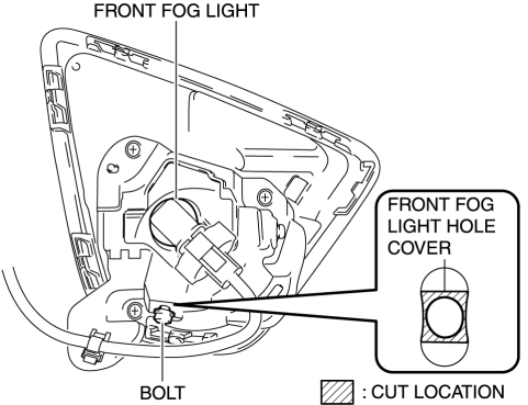
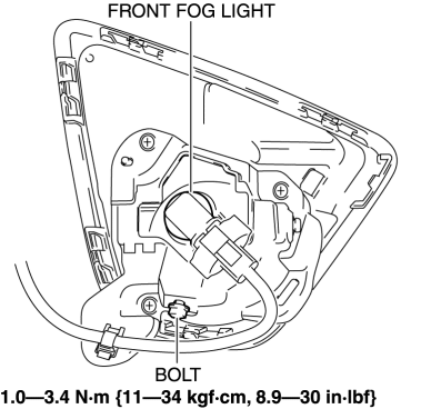
a. Remove the bolt before cutting the front fog light hole cover located on the bolt installation hole.
b. Move the front fog light in the direction of the arrow shown in the figure to secure a space for cutting the front fog light hole cover.
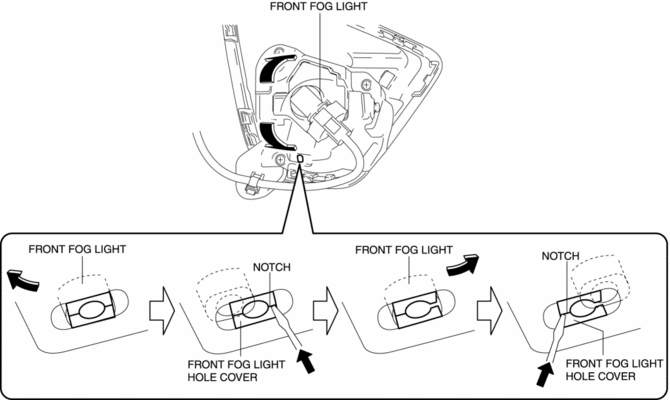
c. Press the notch of the front fog light hole cover using a flathead screwdriver and cutout the front fog light hole cover.
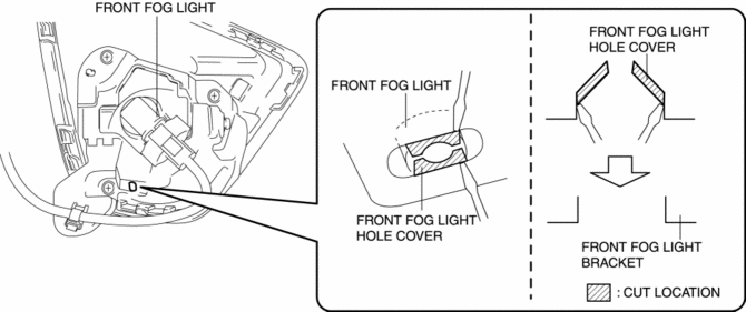
d. Cutout the hatch-marked area of the front fog light hole cover shown in the figure using a flathead screwdriver.
NOTE:
-
Remove all the shaded area shown in the figure so that the front fog light hole cover does not interfere with the bolt.
e. Temporarily tighten the bolt.
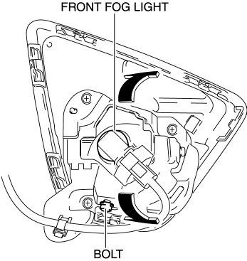
f. Move the front fog light in the direction of the arrow shown in the figure to adjust the brightness border line to the position indicated on the adjustment screen.
g. Tighten the bolt.
 Front Fog Light
Purpose
By shining light in a wider area in front of the vehicle than the light from
the headlights, visibility during poor weather conditions, such as rain and
fog, has been improved. In ...
 Front Fog Light Bulb Removal/Installation
1. Disconnect the negative battery cable..
2. Remove the mudguard screws.
3. Disconnect the connector.
4. Rotate the front fog light bulb in the direction of the arrow (1) shown in
the ...
Other materials:
Precaution [Dynamic Stability Control (DSC)]
1. The ABS warning light and/or brake system warning light and/or TCS/DSC indicator
light and/or TCS OFF indicator light illuminate even when the system is normal.
Warning lights/Indicator lights that may illuminate and/or flash
Cases in which the light may ill ...
Spark Plug Removal/Installation [Skyactiv G 2.0]
CAUTION:
If a spark plug that is not as specified is installed, engine performance
will be deteriorated. Install only the specified spark plug when replacing.
1. Disconnect the negative battery cable..
2. Remove the plug hole plate..
3. Remove the ignition coils..
4. Remove th ...
Brake/Taillight Bulb Removal/Installation
1. Disconnect the negative battery cable..
2. Insert a tape-wrapped flathead screwdriver into the service hole in the position
shown in the figure.
3. Move the flathead screwdriver in the direction of the arrow (1) shown in the
figure, pull out the service hole cover, and detach the serv ...
