Mazda CX-5 Service & Repair Manual: DSC Control
Outline
-
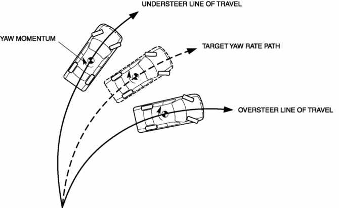
While a vehicle normally turns safely in response to steering operation, there are instances when the limits of tire lateral grip is surpassed due to road surface conditions or vehicle speed, and the influence of evasive steering to avoid an accident or similar situations.
-
Tires surpassing lateral grip exhibit one of the following conditions: Strong oversteer tendency (rear wheel grip is less than front wheels) and Strong understeer tendency (front wheel grip is less than rear wheels)
-
DSC operates at vehicle speeds of approx. 15 km/h {9.3 mph} or more in the conditions described above, controlling engine output and wheel braking to suppress oversteer and understeer tendencies.
Roll over mitigation (ROM) outline
-
The DSC system monitors each sensor and calculates if the vehicle may be approaching a situation where rollover is probable. When this occurs, the DSC system applies preemptive action by adjusting the brake force.
Function
Vehicle condition determination
-
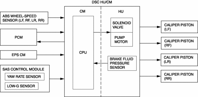
The vehicle speed, steering angle, lateral-G, and yaw rate are detected by the sensors and used in calculations by the DSC HU/CM to determine the vehicle condition. Then, depending on the difference between the target yaw rate, calculated with the values input from each sensor and the value detected by the yaw rate sensor, an oversteer or understeer tendency can be determined.

Oversteer tendency determination
-
When turning, if the actual vehicle yaw rate is larger than the target yaw rate (the yaw rate that should normally be formed as determined by the steering angle and vehicle speed), it means that the vehicle is in or about to be in a spin. Therefore the vehicle is determined to have an oversteer tendency.
Understeer tendency determination
-
When turning, if the actual vehicle yaw rate is less than the target yaw rate (the yaw rate that should normally be formed as determined by the steering angle and vehicle speed), it means that the vehicle is not properly turning. Therefore the vehicle is determined to have an understeer tendency.
Construction
Block diagram

Operation
-
When the DSC HU/CM determines that the vehicle has a strong oversteer or understeer tendency, engine output is lowered and, at the same time, it suppresses the yaw moment by affecting the braking of the front or rear wheels to inhibit the oversteer or understeer tendency.
Oversteer tendency suppression
-
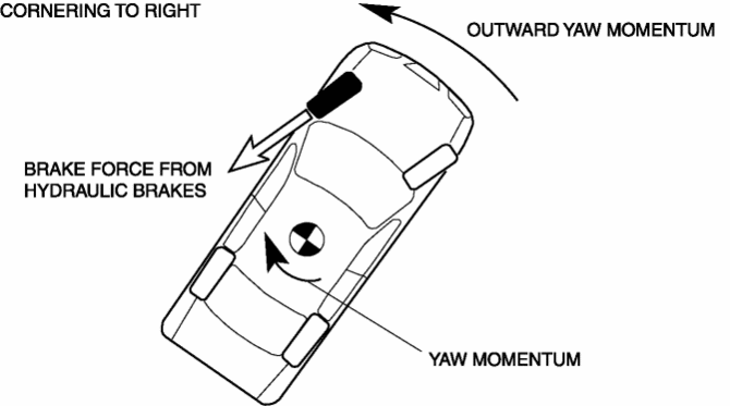
When a large oversteer tendency is determined, braking is applied to the outer front wheel according to the degree of the tendency. As a result, a yaw moment is formed towards the outer side of the vehicle and the oversteer tendency is suppressed.

Understeer tendency suppression
-
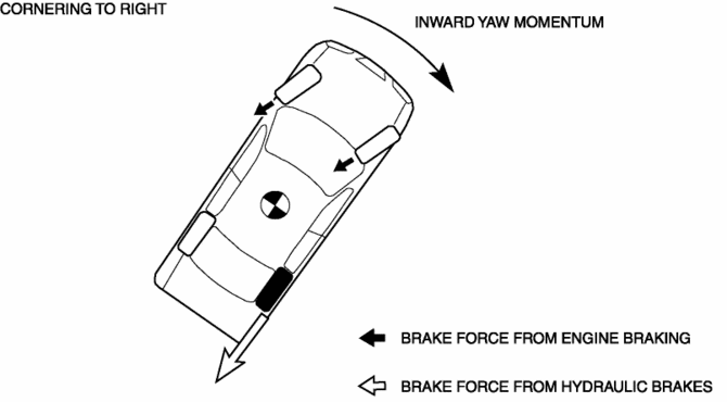
When a large understeer tendency is determined, engine output is controlled and braking is applied to the inner rear wheel according to the degree of the tendency. As a result, a yaw moment is formed towards the inner side of the vehicle and the understeer tendency is suppressed.

Roll over mitigation (ROM) operation
-
The DSC system monitors the signal from yaw rate sensor, low-G sensor, and each sensor, and calculates if the vehicle may be approaching a situation where rollover is probable. When this occur, the DSC system applies preemptive action by roll over mitigation (ROM) function. When the roll over mitigation (ROM) is activated, it adjusts the brake force of specific wheels in response to the direct measurement of the vehicle roll motion. By adjusting the brake force, the DSC system can reduce cornering forces, reducing the total roll moment acting on the vehicle. The DSC system has an additional program within the DSC HU/CM to support the vehicle control during sudden steering operation. The computer uses information from the ABS wheel-speed sensor (wheel speed), EPS CM (steering wheel angle), yaw rate sensor (yaw rate), low-G sensor (lateral-G) and actual engine torque. If the DSC HU/CM determines from all these inputs that conditions exist for a potential rollover, the HU/CM applies one or more brakes and reduces the engine torque to make the vehicle more stable.
 DSC HU/CM
Outline
A high reliability, reduced size and weight DSC HU/CM, integrating both the
DSC HU and the DSC CM, has been adopted.
DSC HU Part Purpose/Function
According to DSC ...
Other materials:
Oil Pressure Switch Removal/Installation [Fw6 A EL, Fw6 Ax EL]
WARNING:
A hot transaxle and ATF can cause severe burns. Turn off the engine and wait
until they are cool.
Always wear protective eye wear when using the air compressor. If the air
compressor is used, any particles of dirt or soiling could spatter and get into
the eyes.
...
Awd Control Module Configuration
CAUTION:
When performing configuration, it is necessary to read the coupling component
calibration data from the AWD control module before replacing it. Connect the
M-MDS to the vehicle and perform vehicle identification before removing the
AWD control module. The coupling component ...
Clutch Fluid Inspection [C66 M R]
NOTE:
A common reserve tank is used for the clutch system and brake system.
1. Verify that the clutch fluid is between the MIN mark and the MAX mark.
Verify that there is no clutch fluid leakage then add clutch fluid to the
level between the MIN mark and the MAX mark..
...

