Mazda CX-5 Service & Repair Manual: Curtain Air Bag Module [Standard Deployment Control System]
Purpose
-
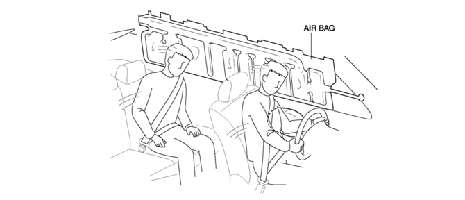
When a curtain air bag module receives an impact from a lateral collision, the operation (deployment) of the air bag mediates the impact to the head of the driver and front passenger.
Function
-
When a curtain air bag module receives an impact from a lateral collision, the air bag is operated (deployed) by the operation signal sent from the SAS control module.
Construction
-
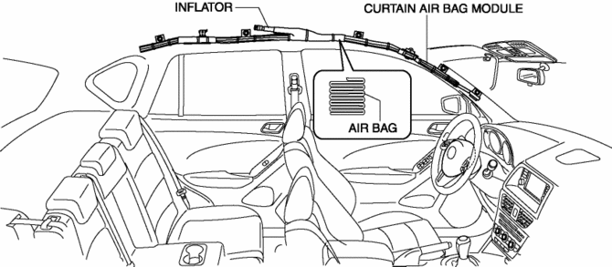
The curtain air bag module is installed along the roof edge between the A and C pillars.
-
The curtain air bag module consists of the inflator and air bag.
-
A stored-type curtain air bag has been adopted which does not use an ignition agent for the inflator.
Operation
-
The curtain air bag module operates (deploys) the air bag by activating the internal inflator.
-
The inflator operates (deploys) in the following order:
1. When an operation (deployment) signal is received from the SAS control module, the igniter built into the inflator generates heat and ignites the ignition agent.
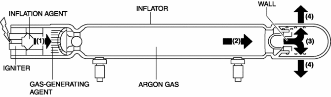
2. The combustion of the ignition agent causes the ignition of a gas agent. The section of the wall from which the air bag deploys is broken by this impact wave.
3. The gas generated by the sealed argon gas and gas-generating agent is cooled at the filter and the filtrate is injected into the air bag.
4. When a curtain air bag operates (deploys), the A-pillar trim and headliner are spread apart by the compressed gas generated from the inflator, inflating the air bag.
Fail-safe
-
Function not equipped.
 Curtain Air Bag Module Removal/Installation [Standard Deployment Control System]
WARNING:
Handling the air bag module improperly can accidentally deploy the air bag
module, which may seriously injure you. Read the air bag system service warnings
and cautions before h ...
 Drive By Wire Control
Outline
Calculates the optimum target throttle valve opening angle at all engine
speeds and controls the throttle valve actuator.
The drive-by-wire control is composed of the idle ai ...
Other materials:
Shift Pressure Control (Direct Electric Shift Control) [Fw6 A EL, Fw6 Ax EL]
Outline
The TCM drives shift solenoids No.1, 2, 3, 4, the pressure control solenoid,
and the on/off solenoid based on inputs signals from each switch and sensor,
and performs direct electronic control of the clutch engagement pressure. As
a result, precise hydraulic pressure control ...
Main Fuse Removal/Installation
1. Disconnect the negative battery cable..
2. Insert a tape-wrapped flathead screwdriver into the service hole in the position
shown in the figure.
3. Move the flathead screwdriver in the direction of the arrow (1) shown in the
figure, pull up the main fuse cover in the direction of the ...
Ambient Temperature Sensor [Manual Air Conditioner]
Purpose
The ambient temperature sensor detects the ambient temperature.
Function
The ambient temperature sensor converts the detected temperature to an electric
signal.
Construction
A thermistor-type ambient temperature sensor has been adopted.
The ambient ...
