
Mazda CX-5 Service & Repair Manual: Condenser Removal/Installation
1. Disconnect the negative battery cable..
2. Discharge the refrigerant..
3. Remove the front under cover No.1..
4. Drain the engine coolant..
5. Remove the following parts:
a. Plug hole plate.
b. Air cleaner, air hose and fresh air duct component.
c. Coolant reserve tank.
d. Cooling fan component.
e. Radiator.
6. Remove the bolts.
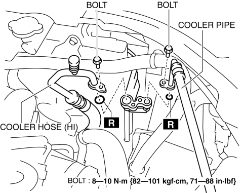
7. Disconnect the cooler hose (HI) and cooler pipe. Do not allow remaining compressor oil in the refrigerant line to spill..
CAUTION:
-
If moisture or foreign material enters the refrigeration cycle, cooling ability will be lowered and abnormal noise or other malfunction could occur. Always plug open fittings immediately after removing any refrigeration cycle parts.
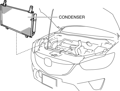
8. Remove the condenser, being careful not to allow remaining compressor oil in the condenser to spill..
CAUTION:
-
If moisture or foreign material enters the refrigeration cycle, cooling ability will be lowered and abnormal noise or other malfunction could occur. Always plug open fittings immediately after removing any refrigeration cycle parts.
9. Install in the reverse order of removal.
10. Inspect for engine coolant leakage..
11. Perform the refrigerant system performance test..
Condenser Installation Note
1. After replacing the condenser, add compressor oil to the refrigeration cycle.
-
Supplemental oil amount (approx. quantity)
-
13 ml {13 cc, 0.44 fl oz}
 Condenser Inspection
1. Inspect the condenser for cracks, damage, and oil leakage.
If there is any malfunction, replace the condenser.
2. Visually inspect for bent fins for clogging of foreign material.
...
 Condenser Removal/Installation
1. Disconnect the negative battery cable..
2. Remove the following parts:
a. Trunk board.
b. Trunk end trim (LH).
c. Rear scuff plate (LH).
d. Trunk side trim (LH).
e. D-pillar trim (LH). ...
Other materials:
How To Use This Manual
Range of Topics
This manual contains procedures for performing all required service operations.
The procedures are divided into the following five basic operations:
Removal/Installation
Disassembly/Assembly
Replacement
Inspection
Adj ...
Power Window Main Switch
Purpose
Remote control of door glass open/close and power outer mirror adjustment
are possible with occupant seated in the cabin.
Function
Power window main switch
Manual
When the power window main switch is operated for manual open/close operation,
it sends ...
Hazard Warning Switch Inspection
1. Disconnect the negative battery cable..
2. Remove the decoration panel..
3. Verify that the continuity between the hazard warning switch terminals is
as indicated in the table.
If the continuity is as indicated in the table, go to the next step.
If not as indicated i ...
