Mazda CX-5 Service & Repair Manual: Compression Inspection
WARNING:
-
Hot engines and oil can cause severe burns. Be careful not to burn yourself during removal/installation of each component.
-
Fuel vapor is hazardous. It can very easily ignite, causing serious injury and damage. Always keep sparks and flames away from fuel.
-
Fuel line spills and leakage are dangerous. Fuel can ignite and cause serious injuries or death and damage. Fuel can also irritate skin and eyes. To prevent this, always complete the “Fuel Line Safety Procedure”..
1. Verify that the battery is fully charged..
-
Recharge it if necessary..
2. Warm up the engine to the normal operating temperature.
3. Perform “Fuel Line Safety Procedures”..
4. Remove the following parts.
a. Plug hole plate..
b. Ignition coil/ion sensors..
c. Spark plugs..
d. Fuel pump relay
e. Fuel injector relay
5. Measure the compression pressure using the following procedure.
a. Press a compression gauge into the spark plug hole.
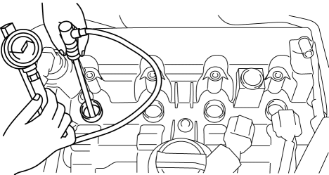
b. Fully depress the accelerator pedal.
c. Crank the engine and measure the compression pressure.
-
Compression
-
Standard: 885 kPa {9.02 kgf/cm2, 128 psi} [300 rpm]
-
Minimum: 708 kPa {7.22 kgf/cm2, 103 psi} [300 rpm]
-
Maximum difference between cylinders: 150 kPa {1.53 kgf/cm2, 21.8 psi}
NOTE:
-
Because the SKYACTIV-G 2.0 retards the intake valve closing timing, compression pressure is low.
d. Perform Steps (1) to (3) for all cylinders.
e. If it is less than the minimum specification, or there is a cylinder with a maximum value that exceeds the other cylinders, add a small quantity of engine oil through the spark plug hole and perform Steps (1) to (3).
-
If the pressure increases by adding the engine oil, the piston ring or the cylinder surface is worn, or they are damaged. Perform overhaul servicing.
-
If the pressure does not increase, valve seizure, valve attachment malfunction, or pressure leakage from the cylinder head gasket might be occurring. Perform overhaul servicing.
f. If the measured value is high, it is possible that there is an error in the electric variable valve timing system.
6. Remove the compression gauge.
7. Install the following parts.
a. Fuel injector relay
b. Fuel pump relay
c. Spark plugs..
d. Ignition coil/ion sensors..
e. Plug hole plate..
 General
...
 Compression Inspection
WARNING:
Hot engines and oil can cause severe burns. Be careful not to burn yourself
during removal/installation of each component.
Fuel vapor is hazardous. It can very easily ignit ...
Other materials:
Front Fog Light Bulb Removal/Installation
1. Disconnect the negative battery cable..
2. Remove the mudguard screws.
3. Disconnect the connector.
4. Rotate the front fog light bulb in the direction of the arrow (1) shown in
the figure and remove it from the front fog light in the direction of the arrow
(2) shown in the figu ...
High Clutch [Fw6 A EL, Fw6 Ax EL]
Purpose/Function
The high clutch operates in 4GR, 5GR, and 6GR and intermittently operates
the rear carrier by drive force from the turbine shaft.
For the high clutch, a centrifugal balance clutch has been adopted to prevent
clutch drag and to assure stabilized piston thrust in ...
Rear Drive Shaft Disassembly/Assembly
1. Disassemble in the order indicated in the table.
2. Assemble in the reverse order of disassembly.
1
Boot band (differential side)
(See Boot Band (Differential Side) Disassembly Note.)
(See Boot Band (Differential Side) Assembly Note.)
2
...
