Mazda CX-5 Service & Repair Manual: Brake Fluid Pressure Sensor Inspection
1. Switch the ignition to off.
2. Remove the clips.
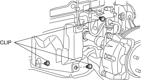
3. Set the splash shield out of the way.
4. Disconnect the brake pipe from the LF brake hose.
5. Remove the clip.
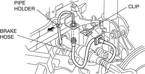
6. Remove the LF brake hose from the bracket.
7. Detach the brake pipe from the pipe holder.
8. Install the SST
to the brake pipe as shown in the figure.
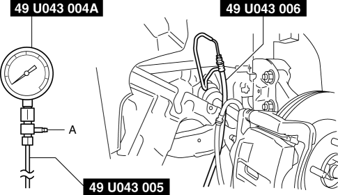
9. Bleed the brake line and the SSTs
of air. Bleed the air form the SSTs
using bleeder screw A.
10. Connect the M-MDS to the DLC-2.
11. Select the “BRK_F_P_R” PID.
12. Start the engine.
13. Depress the brake pedal, and confirm that the fluid pressure value of the SST
(Gauge) and the value shown on the M-MDS are equal
-
If the fluid pressures are different, replace the DSC HU/CM..
14. After the inspection, remove the SSTs
, install the brake hose, clamp, and brake pipe to the original positions, and then bleed the air from the brake line..
 Brake Fluid Pressure Sensor
Purpose/Function
The brake fluid pressure sensor detects the fluid pressure from the master
cylinder and transmits it to the DSC HU/CM.
Construction
The brake fluid pressure sen ...
 Brake Hose (Front) Removal/Installation
1. Remove in the order indicated in the table.
2. Install in the reverse order of removal.
3. After installation, add brake fluid, bleed the air, and inspect for fluid
leakage..
...
Other materials:
Front Door Key Cylinder Switch Inspection
1. Perform the front door glass preparation..
2. Disconnect the negative battery cable..
3. Remove the following parts:
a. Inner garnish.
b. Front door trim.
c. Front door key cylinder.
d. Front door glass.
e. Front door module panel.
f. Front door latch and lock actuator.
Front Do ...
Cooling System
Outline
Passing water resistance is reduced by improvement of the engine coolant
passage shape.
Pump efficiency is improved by changing the water pump impeller to the closed
impeller.
Structural View
Flow Chart
Structure
Consists of the followi ...
Starter Disassembly/Assembly [Skyactiv G 2.0]
1. Disassemble in the order indicated in the table.
2. Assemble in the reverse order of disassembly.
1
Magnetic switch
2
Adjustment washer
3
Rear housing
4
Brush and brush holder
...
