Mazda CX-5 Service & Repair Manual: Ambient Temperature Display
Purpose
-
The ambient temperature display notifies the user of the ambient temperature.
Function
-
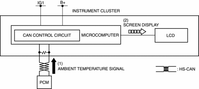
The instrument cluster displays the ambient temperature based on the ambient temperature signal sent from the PCM as a CAN signal.
-
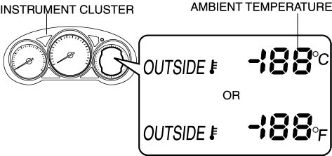
The ambient temperature is displayed between -40—70°C {-40?160°F} If the ambient temperature is -40°C {-40°F} or less, -40°C {-40°F} is displayed, and 70°C {160°F} is displayed if the temperature is 70°C {160°F} or more.
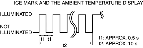
Road ice warning function
-
When the instrument cluster receives an ambient temperature signal of 4°C {39°F} or less from the PCM, it displays the ice mark. After receiving the ambient temperature signal of 4°C {39°F} or more, it flashes the ice mark and the ambient temperature display for about 10 s to warn the user that the road surface may be icy.
-
Once the instrument cluster performs the road ice warning, it will not perform it again until it receives an ambient temperature of 6°C {43°F} or more.
-
The ice mark and ambient temperature flashing pattern is as indicated in the figure.
Ambient temperature display switching function
-
The ambient temperature display can be switched between Celsius and Fahrenheit display. Refer to the workshop manual for the ambient temperature display switching procedure.
Construction
-
The ambient temperature is displayed on the LCD in the instrument cluster.
Operation
1. When the ignition is switched ON, the instrument cluster receives an ambient temperature signal from the PCM (1).
2. Based on the ambient temperature signal, the instrument cluster displays the ambient temperature and ice mark on the LCD.
Fail-safe
-
Function not equipped.
 Gauges
...
 Ambient Temperature Display Switching Procedure
NOTE:
When the ambient temperature display is switched, the set A/C cabin temperature
display is also changed.
...
Other materials:
Accelerator Pedal Position (App) Sensor Inspection
Voltage Inspection
NOTE:
Because the APP sensor is integrated in the accelerator pedal, replacing
the APP sensor includes replacement of the accelerator pedal.
1. Connect the M-MDS to the DLC?2.
2. Switch the ignition ON (engine off or on).
3. Verify that the APP sensor output ...
Suspension Features
Improved rigidity and handling stability
A strut type front suspension adopted
E-type multi-link rear suspension adopted
For the front/rear crossmembers, the welded flange has been eliminated
(flange-less), the cross-section expa ...
Engine Oil Solenoid Valve Inspection
Engine Oil Solenoid Valve Operation Inspection
1. Remove the engine oil solenoid valve..
2. Verify that the battery is fully charged.
3. Connect the battery to the engine oil solenoid valve connector (2 terminals)
as shown in the figure.
4. Verify that there is an operation sound from t ...
