Mazda CX-5 Service & Repair Manual: Adaptive Front Lighting System (Afs) Control Module Removal/Installation
NOTE:
-
The AFS control module prior to replacement stores the vehicle specification information.
-
A new AFS control module does not store any vehicle specification information.
-
When the ignition is switched ON after the AFS control module is replaced, the AFS control module reads the vehicle specification information sent via CAN transmission from the instrument cluster using the automatic configuration function, and stores it.
-
The AFS control module records the vehicle height while it is unoccupied.
-
The new AFS control module does not record the vehicle height while it is unoccupied.
1. Disconnect the negative battery cable..
2. Remove the front scuff plate (LH)..
3. Remove the front side trim (LH)..
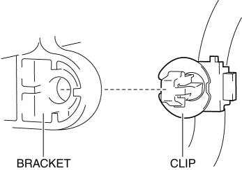
4. While pressing the clip tab in the direction of arrows (1) shown in the figure, press the clip in the direction of arrow (2) to detach the clip tab and the bracket.
NOTE:
-
Because the AFS control module cannot be removed with the clip installed to the bracket, remove the clip from the bracket to allow for a margin length in the wiring harness.
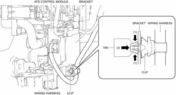
5. Remove the clip.
6. While pressing the bracket tab in the direction of the arrows (3) shown in the figure using a tape-wrapped flathead screwdriver, hold the connector, pull out the AFS control module in the direction of the arrow (4) shown in the figure to detach the bracket tab and AFS control module.
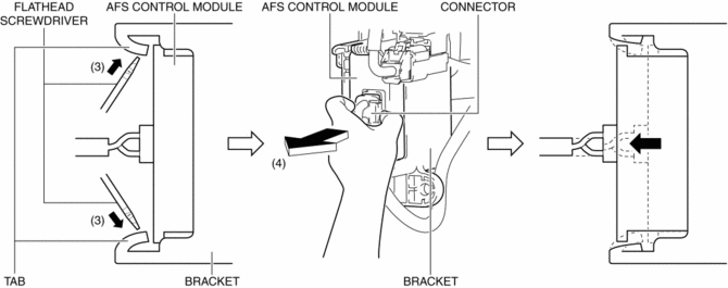
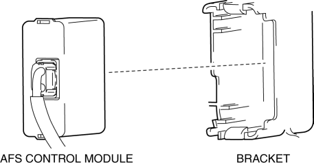
7. Remove the AFS control module.
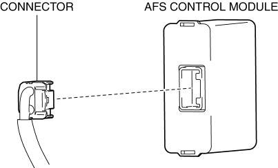
8. Disconnect the connector.
9. Install in the reverse order of removal.
10. Switch the ignition ON and perform the AFS control module automatic configuration.
11. Clear the DTCs.
12. If the AFS control module is replaced with a new one, perform the auto leveling system initial setting..
 Exterior
...
 Afs (Adaptive Front Lighting System)
Outline
The AFS is a system which enhances the range of visibility when the headlights
are turned on by pointing the optical axis of the headlights in the direction
in which the vehicle i ...
Other materials:
Side Turn Light
Purpose
The side turn lights are used to signal vehicles/people at the side of the
vehicle that the vehicle is going to make a right or left turn.
Function
The side turn lights flash according to the operation of the turn or the
hazard switch.
Construction
Side ...
Awd Warning Light
Purpose, Function
Warns the driver of a AWD system malfunction.
Construction
The AWD warning light is built into the instrument cluster.
Operation
If the self-diagnostic function stores a DTC, the warning light illuminates
to alert the driver of the malfunct ...
Front Seat Adjuster Unit Removal/Installation
WARNING:
Handling a side air bag improperly can accidentally operate (deploy) the
air bag, which may seriously injure you. Read the service warnings/cautions
in the Workshop Manual before handling the front seat (side air bag integrated)..
If the sliding mechanisms on both side ...
