Mazda CX-5 Service & Repair Manual: ABS Wheel Speed Sensor And ABS Sensor Rotor
Purpose/Function
-
The ABS wheel-speed sensor and ABS sensor rotor detect the rotation condition of each wheel and transmit this information to the DSC HU/CM.
-
The signal from the ABS wheel-speed sensor is the primary signal that the DSC HU/CM uses when carrying out control.
Construction
-
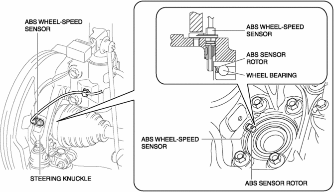
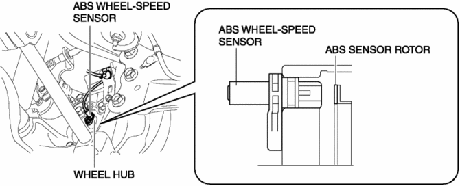
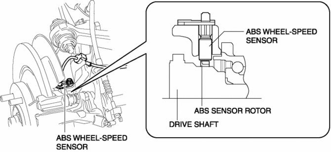
The ABS wheel-speed sensor utilizes a semi-conductor element that contains an active drive circuit (MR element*). The front sensor is installed on the steering knuckle and the rear sensor is installed on the wheel hub (2WD) or hub support (AWD).
-
The front ABS sensor rotor utilizes a magnetic encoder system that functions with magnetic rubber, and is integrated into the front wheel hub. Therefore, if there is any malfunction of the front ABS sensor rotor, replace the front wheel hub.
-
The rear ABS sensor rotor utilizes a magnetic encoder system that functions with magnetic rubber, and is integrated into the rear wheel hub (2WD) or shaft and ball joint component (AWD). Therefore, if there is any malfunction of the rear ABS sensor rotor, replace the rear wheel hub (2WD) or shaft and ball joint component (AWD).
*: A magneto-resistive force means that an exterior magnetic field acts on the element, changing the resistance of the element.
CAUTION:
-
When inspecting the ABS wheel-speed sensor, do not use a tester to inspect resistance. It is possible that the voltage from the tester could damage the semiconductor inside the ABS wheel-speed sensor. Inspect using the PID data monitor of the Mazda modular diagnostic system (M-MDS).
NOTE:
-
Magnetic encoder: A plate that has positive and negative poles (marked out) in a continuous, alternating line.
Front ABS wheel-speed sensor and sensor rotor
Rear ABS wheel-speed sensor and sensor rotor (2WD)
Rear ABS wheel-speed sensor and sensor rotor (AWD)
Operation
-
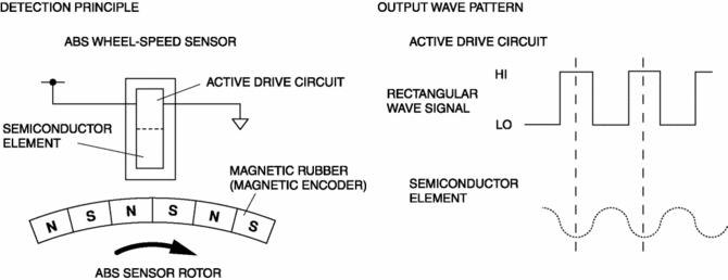
As the ABS sensor rotor rotates, the magnetic flux between the ABS wheel-speed sensor and the ABS sensor rotor change periodically. This periodic change is in proportion to the rotation speed.
-
The semiconductor element in the wheel speed sensor detects the change in magnetic flux, and the active drive circuit converts it to a rectangular wave signal for the current, which is transmitted to the DSC HU/CM.
-
For every single rotation of the ABS sensor rotor, 44 rectangular wave pulse signals are output. The CM in the DSC HU/CM calculates the wheel speed from the periodicity of these pulses.
Fail-safe
|
DTC No. |
Fail-safe function |
|
C0030:07 |
|
|
C0031:07 |
|
|
C0031:11 |
|
|
C0031:15 |
|
|
C0031:29 |
|
|
C0031:2F |
|
|
C0031:64 |
|
|
C0033:07 |
|
|
C0034:07 |
|
|
C0034:11 |
|
|
C0034:15 |
|
|
C0034:29 |
|
|
C0034:2F |
|
|
C0034:64 |
|
|
C0036:07 |
|
|
C0037:07 |
|
|
C0037:11 |
|
|
C0037:15 |
|
|
C0037:29 |
|
|
C0037:2F |
|
|
C0037:64 |
|
|
C0039:07 |
|
|
C003A:07 |
|
|
C003A:11 |
|
|
C003A:15 |
|
|
C003A:29 |
|
|
C003A:2F |
|
|
C003A:64 |
 Up Switch [Fw6 A EL, Fw6 Ax EL]
Purpose/Function
The up switch detects the shift up operation of the selector lever.
The up switch signal is sent to the TCM via CAN and is used for manual shift
control and engine-t ...
 Accelerator Pedal, Kickdown Switch [Skyactiv G 2.0]
Purpose, Function
The driver's intentions are transmitted to the PCM via the accelerator pedal.
Kickdown switch (ATX) (Applied VIN (assumed): JM3 KE2*E*D# 148107?)
If the acce ...
Other materials:
Torque Box Installation [Panel Replacement]
Symbol Mark
Installation Procedure
1. When installing new parts, measure and adjust the body as necessary to conform
with standard dimensions.
2. Drill holes for the plug welding before installing the new parts.
3. After temporarily installing new parts, make sure the related parts fit p ...
Oil Filter
Purpose, Function
Engine oil is filtered by passing engine oil through the oil filter element.
Construction
The oil filter is installed on the right side surface of the cylinder block.
A spin-on type (full-flow type) oil filter has been adopted.
The bypa ...
Rear Door Speaker Inspection
1. Disconnect the negative battery cable..
2. Remove the rear door trim..
3. Disconnect the rear door speaker connector..
4. Verify that the resistance between the rear door speaker terminals is as indicated
in the table.
If not as indicated in the table, replace the rear door sp ...
