Mazda CX-5 Service & Repair Manual: Windshield Wiper Motor And Link Removal/Installation
1. Disconnect the negative battery cable..
2. Remove the following parts:
a. Windshield wiper arm and blade.
b. Cowl grille.
CAUTION:
-
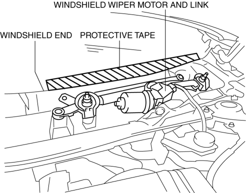
Always affix protective tape to the windshield end. If the windshield wiper motor and link contacts the windshield, it could damage the windshield.
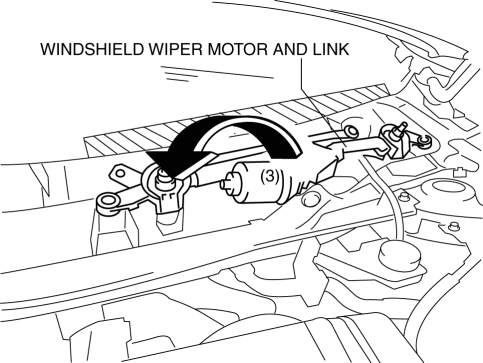
3. Affix protective tape to the area where the windshield end interferes with the windshield motor and link as shown in the figure.
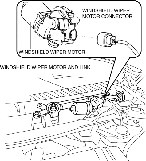
4. Disconnect the windshield wiper motor connector.
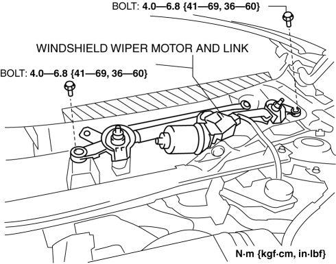
5. Remove bolts.
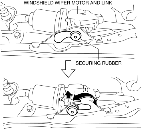
6. Move the windshield wiper motor and link in the order of the arrows (1) and (2) to remove the securing rubber from the vehicle.
7. Remove the windshield wiper motor and link from the vehicle in the direction of the arrow (3) while being careful not to allow the windshield wiper end to interfere with the windshield wiper motor and link.
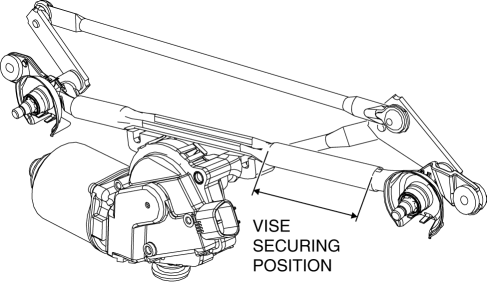
8. Fix the position of the windshield wiper link shown in the figure with a vise.
CAUTION:
-
If the vise is tightened with excessive force, it could deform or damage the windshield wiper link. When securing the windshield wiper link in the vise, be careful not to deform or damage the windshield wiper link.
-
Protect the windshield wiper link by placing a rag in the vise when securing it in the vise. Otherwise, it could damage the vise securing position.
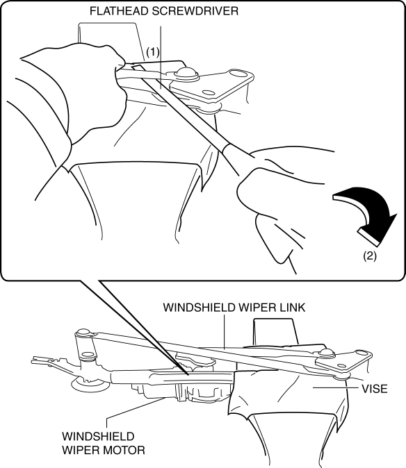
9. Insert a tape-wrapped flathead screwdriver into the (1) position, move the flathead screwdriver in the direction of the arrow (2), and remove the windshield wiper motor and ball joint for the windshield wiper link.
10. Remove bolts securing the windshield wiper motor and windshield wiper link, and remove nuts from windshield wiper motor.
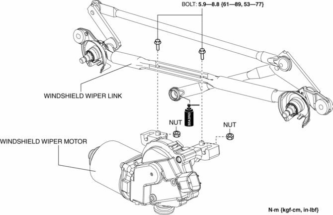
11. Remove the windshield wiper motor from the windshield wiper link.
12. Install in the reverse order of removal..
Ball Joint Assembly Note
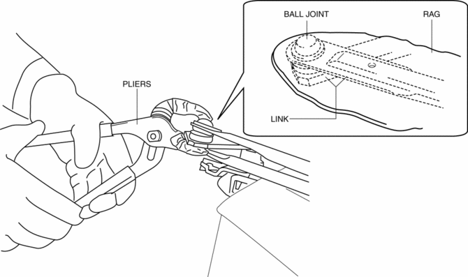
1. When assembling the ball joint, use a clean rag to protect the link and squeeze using a pair of protective tape-wrapped pliers.
 Windshield Wiper Motor
Purpose
The windshield wiper motor transmits rotation force to the windshield wiper
link to operate the windshield wiper arms and blades.
Function
The windshield wiper motor ope ...
 Windshield Wiper Motor Inspection
1. Disconnect the negative battery cable..
2. Remove the following parts:
a. Windshield wiper arm and blade.
b. Cowl grille.
Windshield Wiper Motor Inspection
1. Apply battery positive voltag ...
Other materials:
Floor Under Cover Removal/Installation
1. Lift up the vehicle.
2. Remove bolts A.
3. Remove fasteners B.
4. Remove the floor under cover No.1.
5. Remove nuts C.
6. Remove fasteners D.
7. Remove bolts E.
8. Remove the floor under cover No.2.
9. Remove bolts F.
10. Remove the fastener G.
11. Remove the floor ...
Oil Seal (Coupling Component) Replacement
1. Drain the differential oil into a container.
2. Remove the coupling component..
3. Remove the oil seal from the differential carrier using a screwdriver or similar
tool.
4. Apply differential oil to the new oil seal lip.
5. Install the new oil seal to the differential carrier using the ...
Front Heat Duct Removal/Installation
1. Disconnect the negative battery cable..
2. Remove the following parts:
a. Dashboard under cover.
b. Side wall.
c. Glove compartment.
3. Detach the tab and remove the front heat duct.
LH
RH
4. Install in the reverse order of removal. ...
