Mazda CX-5 Service & Repair Manual: Upper Cowl Side Reinforcement Removal [Panel Replacement]
Symbol Mark
Removal Procedure
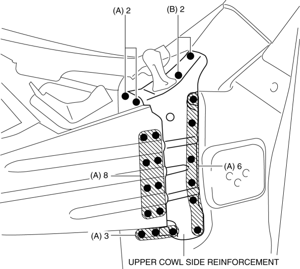
1. Drill the 13 locations indicated by (A) shown in the figure.
2. Drill the 8 locations indicated by (B) shown in the figure.
NOTE:
-
When a drill the 8 locations indicated by (B) shown in the figure, the through hole is not made in consideration of the workability at the installing.
3. Remove the upper cowl side reinforcement.
 Upper Cowl Side Reinforcement Installation [Panel Replacement]
Symbol Mark
Installation Procedure
1. When installing new parts, measure and adjust the body as necessary to conform
with standard dimensions.
2. Drill holes for the plug welding before inst ...
 Ventilator Grille Removal/Installation
Side Ventilator Grille
Driver-side
1. Disconnect the negative battery cable..
2. Remove the switch panel..
3. Insert your hand from the area where the switch panel was installed, remove
the si ...
Other materials:
Keyless Antenna [Keyless Entry System]
Purpose
Outputs a request signal and specifies the remote transmitter location.
Function
The keyless antennas output request signals based on the signals from the
start stop unit.
Construction, Operation
Request signals are output by the keyless antenna installed ...
Air Bag Module And Pre Tensioner Seat Belt Deployment Procedures [Two Step Deployment
Control System]
WARNING:
A live (undeployed) air bag module, pre-tensioner seat belt or lap pre-tensioner
seat belt may accidentally operate (deploy) when it is disposed of and cause
serious injury. Do not dispose of a live (undeployed) air bag module, pre-tensioner
seat belt or lap pre-tensioner s ...
Pre Tensioner Seat Belt [Two Step Deployment Control System]
Purpose
The pre-tensioner seat belt retracts and tightens the seat belt webbing to
protect the front passengers during a collision.
Function
The pre-tensioner seat belts operate (deploy) based on the operation signal
from the SAS control module to instantly retract and tigh ...
