Mazda CX-5 Service & Repair Manual: Trip Computer Information System
Outline
-
The trip computer system displays the instantaneous fuel economy, average fuel economy, remaining distance to empty, and the average vehicle speed.
-
The instrument cluster performs trip computer system fail-safe..
Function
-
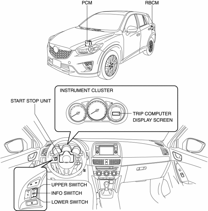
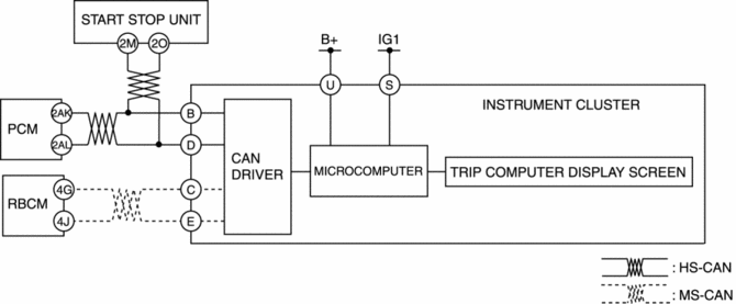
The instrument cluster controls the trip computer system based on the following CAN signals.
-
Vehicle speed signal, fuel injection amount signal, traveled distance signal sent from PCM
-
Fuel gauge sender unit voltage signal sent from rear body control module (RBCM)
-
Steering switch operation signal sent from start stop unit
Instantaneous fuel economy calculation function
-
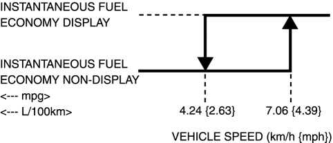
The instrument cluster calculates the instantaneous fuel economy based on the fuel consumption and traveled distance over the past 2 s when the vehicle speed is at the set value or more. In addition, the calculation results are updated every 2 s.
Instantaneous fuel economy formula

-
When there is no fuel consumption, such as during engine braking, <0.0 L/100 km> or <99.9 mpg> is displayed.
-
The instantaneous fuel economy is displayed when the vehicle speed is 7.06 km/h {4.39 mph} or more, and <--- L/100 km> or <--- mpg> is displayed when the vehicle speed is 4.24 km/h {2.63 mph} or less.
Average fuel economy calculation function
-
The instrument cluster calculates the average fuel economy based on the traveled distance and fuel consumption from connecting the battery or resetting the average fuel economy. In addition, the calculation results are updated every minute.
Average fuel economy formula

-
If the cumulative traveled distance is 0 km, <0.0 mpg> or <99.9 L/100 km> is displayed.
-
If the INFO switch is pressed for approx. 1.5 s or more while the average fuel economy is displayed, the cumulative fuel economy and cumulative traveled distance data are reset.
-
If tripmeter A is reset, the average fuel economy is also reset.
-
During the 1 min period after the data has been reset, <--- mpg> or <--- L/100 km> is displayed.
Remaining travel distance calculation function
-
The instrument cluster calculates the remaining travel distance based on the instantaneous fuel economy, cumulative fuel economy and the fuel tank level. In addition, the calculation results are updated every second.
Remaining travel distance formula

-
When the fuel tank level reaches 6 L {2 US gal, 1 Imp gal} or less, the instrument cluster displays <0 km> or <0 miles>.
Average vehicle speed calculation function
-
The instrument cluster calculates the average vehicle speed based on the cumulative traveled distance and cumulative traveled time from connecting the battery or resetting the average vehicle speed. In addition, the calculation results are updated every 10 s.
Average vehicle speed formula

-
If the INFO switch is pressed for approx.1.5 s or more while the average vehicle speed is displayed, the average vehicle speed (cumulative traveled distance and cumulative traveled time data) is reset.
-
During the 1 min period after the data has been reset, <--- km/h> or <--- mph> is displayed.
Structural view
System wiring diagram
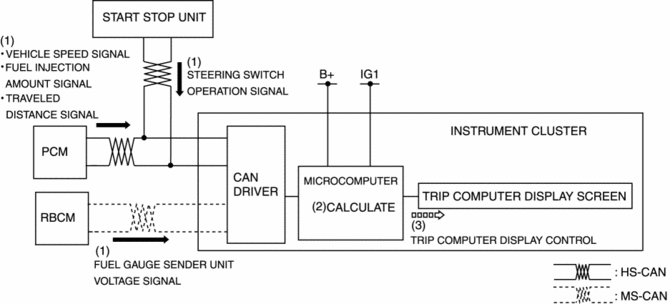
Operation
-
When the ignition is switched ON (engine on), the instrument cluster receives (1) the vehicle speed signal, fuel injection amount signal, traveled distance signal from the PCM, the fuel gauge sender unit voltage signal from the rear body control module (RBCM), and the steering switch operation signal from the start stop unit.
-
The instrument cluster microcomputer calculates (2) the instantaneous fuel economy and average fuel economy based on the received data.
-
The instrument cluster microcomputer displays (3) the calculated results in the trip computer display screen.
Trip computer display switching operation
-
The instrument cluster switches the trip computer display content as follows based on the steering switch operation signal from the start stop unit.
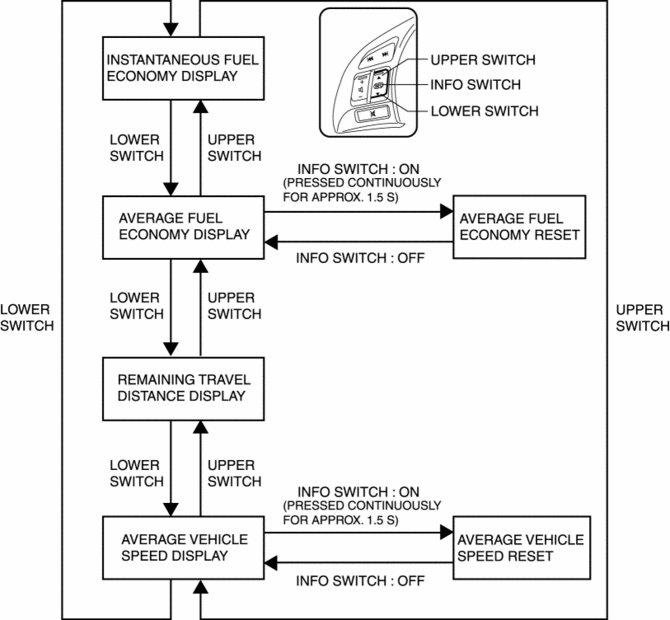
Display screen table

 Tachometer
Purpose
The tachometer notifies the driver of the engine speed.
Function
The instrument cluster controls the tachometer needle based on the engine
speed signal from the PCM and ...
 Body Interior
...
Other materials:
PCM Inspection
Without Using the M-MDS
NOTE:
Because the PCM uses a waterproof connector, the inspection for the voltage/wave
pattern cannot be performed. The following values are for reference.
Terminal voltage table (Reference)
Terminal
Signal
C ...
Electric Variable Valve Timing Actuator
Purpose, Function
The electric variable valve timing actuator changes the phases of the intake
camshaft relative to the crankshaft. As a result, the open/close period of the
intake valve is changed, optimized valve timing in accordance with driving conditions
is realized, output is i ...
Driveline/Axle Features
Improved driveability
Bell-shaped constant velocity joint adopted for wheel-side joint
of front and rear drive shaft
Tripod-shaped constant velocity joint adopted for differential-side
joint of front drive shaft (ATX) and rear drive shaft
...
