Mazda CX-5 Service & Repair Manual: Steering Column And Shaft
Purpose/Function
-
The steering input force, generated when the driver operates the steering wheel, is transmitted to the steering gear.
Construction
-
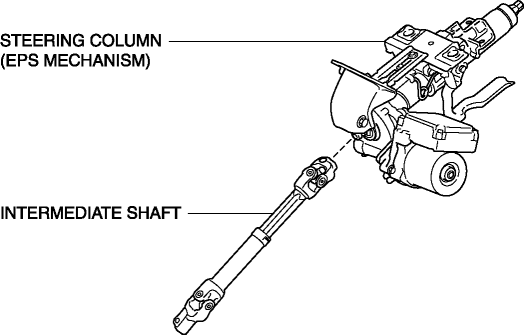
The steering column and shaft consists of the steering column with a built-in EPS mechanism and the intermediate shaft.
-
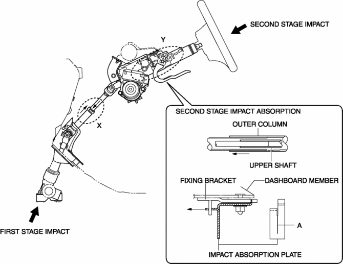
As a result of impact absorbing mechanisms on the steering column and intermediate shaft, when a collision occurs, the steering shaft effectively absorbs the impact energy that would be transmitted to the driver, thereby reducing injury.
-
Due to the adoption of a tilt/telescope mechanism for the steering shaft on all vehicles, operability has been improved.

Operation
-
EPS mechanism
-
Based on the steering torque signal from the torque sensor and the vehicle speed and engine speed signals from the PCM, the EPS CM drives the EPS motor and transmits the assist torque to the intermediate shaft via the deceleration mechanism.
-
Energy absorbing system
-
At the moment of a collision, when impact energy (first stage impact) is input from the vehicle front due to the rearward collapse of the steering gear, the intermediate shaft contracts to absorb the impact from the driver. (Section X in the figure)
-
When the body of the driver contacts the steering wheel (second stage impact), the fixing bracket comes off the dashboard member, and the upper shaft and the outer column slide forward. At this time, the impact absorption plate (one part secured to instrument panel member, another part to fixing bracket) deforms (area A shown in figure cracks) to absorb the impact to the driver. (Section Y in the figure)

-
Tilt/telescope mechanism
-
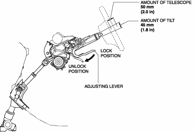
The steering wheel can be moved in the up/down and forward/backward direction when the adjusting lever is pressed towards the front of the vehicle to release the lock of the tilt/telescope system.
-
The tilt/telescope mechanism has a movement range of 45 mm {1.8 in}
(tilt)/ 50 mm {2.0 in}
(telescope) and can be adjusted, without steps, to anywhere in this range.

Fail-safe
-
Function not equipped.
 Wheel, Column
...
 Steering Shaft Inspection
1. Inspect the steering column for excessive play and damage.
2. Verify that the clearance between the projection on the steering column shown
in the figure and the bracket is less than 2.0 mm {0. ...
Other materials:
Oil Seal (Side Gear) Replacement
1. Remove the drain plug and the drain differential oil into a container.
2. Install a new washer and the drain plug, and tighten.
3. Remove the rear drive shaft..
4. Remove the clip from the drive shaft.
CAUTION:
Wrap the end of a screwdriver with cloth to prevent scratches to the i ...
Rear Seat Belt Removal/Installation
CAUTION:
The ELR (emergency locking retractor) has a spring that will unwind if the
retractor cover is removed. The spring cannot be rewound by hand. If this occurs,
the ELR will not work properly. Therefore, do not disassemble the retractor.
1. Remove the following parts:
a. T ...
Antenna Feeder No.1 Inspection
With audio system
1. Disconnect the negative battery cable..
2. Remove the following parts:
a. A-pillar trim (RH).
b. Decoration panel.
c. Audio unit.
3. Disconnect antenna feeder No.2.
4. Verify that the continuity between antenna feeder No.1 terminals is as indicated
in the tabl ...
