
Mazda CX-5 Service & Repair Manual: Slide Motor Removal/Installation
WARNING:
-
Handling a side air bag improperly can accidentally operate (deploy) the air bag, which may seriously injure you. Read the service warnings/cautions in the Workshop Manual before handling the front seat (side air bag integrated)..
-
If the sliding mechanisms on both sides are not locked after assembling the front seat, the front seat will operate accidentally while the vehicle is driven, which could result in serious injury. After assembling the front seat, shake it up and down and verify that the sliding mechanism on the both sides are locked.
CAUTION:
-
If the slide bar is operated after the front seat is removed, the left/right slide positions will deviate and the adjuster unit could be damaged after the front seat is installed. After removing a front seat, do not operate the slider lever.
-
Verify that there are no malfunctions in the forward/back slide of the seat and in the adjuster unit after installing a front seat.
-
When performing the procedure with a front seat removed from the vehicle, perform the procedure on a clean cloth so as not to damage or soil the seat.
1. Switch the ignition off (LOCK).
2. Disconnect the negative battery cable and wait for 1 min
..
3. Remove the following parts:
a. Front seat.
b. Front seat side cover.
c. Front seat adjuster unit.
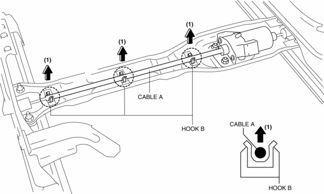
4. Lift up cable A in the direction of the arrow (1) shown in the figure and remove it from the hook B.
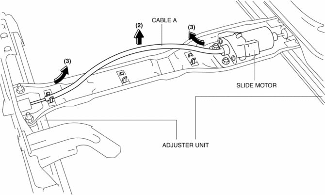
5. Lift up cable A in the direction of the arrow (2) shown in the figure, and pull out the adjuster unit and slide motor in the direction of the arrow (3).
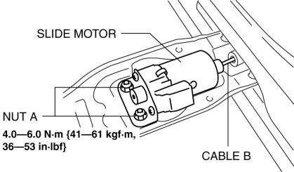
6. Remove nuts A, and remove the slide motor and cable B.
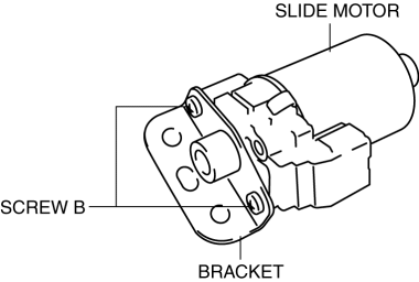
7. Remove screws B, and remove the bracket from the slide motor.
8. Install in the reverse order of removal.
 Slide Motor Inspection
WARNING:
Handling a side air bag improperly can accidentally operate (deploy) the
air bag, which may seriously injure you. Read the service warnings/cautions
in the Workshop Manual befor ...
 Power Seat Switch Inspection
WARNING:
Handling a side air bag improperly can accidentally operate (deploy) the
air bag, which may seriously injure you. Read the service warnings/cautions
in the Workshop Manual befor ...
Other materials:
Front Shock Absorber Disposal
WARNING:
Whenever drilling into a front shock absorber, wear protective eye wear.
The gas in the front shock absorber is pressurized, and could spray metal chips
into the eyes and face when drilling.
1. Place the shock absorber on a level surface or with the piston pointing d ...
Shroud Side Member Installation [Panel Replacement]
Symbol Mark
Installation Procedure
1. When installing new parts, measure and adjust the body as necessary to conform
with standard dimensions.
2. Drill holes for the plug welding before installing the new parts.
3. After temporarily installing new parts, make sure the related parts fit p ...
Shift Point Control (Automatic Shift Control) [Fw6 A EL, Fw6 Ax EL]
Outline
The TCM implements auto shift control according to the vehicle speed and
accelerator pedal depression amount while in D position.
When the vehicle is stopped with the selector lever is in the D position
and the brake pedal depressed, the neutral idle control is performed ...
