
Mazda CX-5 Service & Repair Manual: Side Air Bag Module [Standard Deployment Control System]
Purpose
-
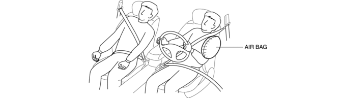
When a side air bag module receives an impact from a lateral collision, the operation (deployment) of the air bag mediates the impact to the chest, stomach, and waist of the driver and front passenger.
Function
-
When a side air bag module receives an impact from a lateral collision, the air bag is operated (deployed) by the operation signal sent from the SAS control module.
Construction
-
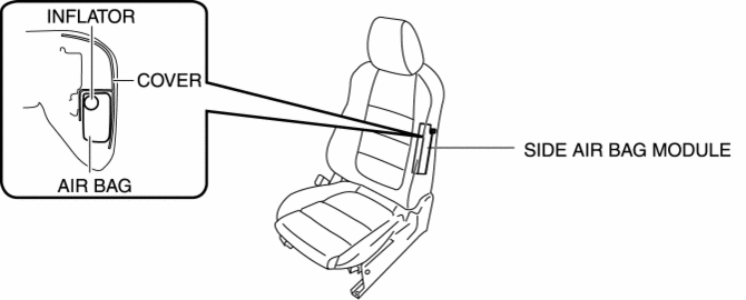
The side air bag modules are installed on the door side of the front seat backs.
-
The side air bag module consists of the inflator and air bag.
Operation
-
The side air bag module operates (deploys) the air bag by activating the internal inflator.
-
The inflator operates (deploys) in the following order:
1. When an operation (deployment) signal is received from the SAS control module, the initiator built into the inflator is ignited which ignites the booster charge.
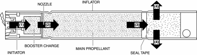
2. The high temperature gas flows into the combustion chamber from the nozzle to ignite the main propellant.
3. The seal tape is broken by the internal pressure in the combustion chamber, and the gas is sprayed out of the inflator through the diffuser (diffusion devise).
4. When the side air bag module operates (deploys), the air bag operates (deploys) while breaking open the seat back trim by the force of gas generated from the inflator.
Fail-safe
-
Function not equipped.
 Side Air Bag Module Removal/Installation [Standard Deployment Control System]
WARNING:
Handling the air bag module improperly can accidentally operate (deploy)
the air bag module, which may seriously injure you. Read the air bag system
service warnings and caution ...
 Side Air Bag Sensor No. 1 Removal/Installation [Standard Deployment Control
System]
Side Air Bag Sensor No. 1 Removal/Installation [Standard Deployment Control
System]
WARNING:
Handling the side air bag sensor improperly can accidentally operate (deploy)
the air bag module, which may seriously injure you. Read the air bag system
service warnings and ca ...
Other materials:
Clutch Disc Inspection [C66 M R]
Operation Inspection
1. Inspect the lining surface for discoloration and grease adhesion.
2. Inspect the torsion spring for weakness and the rivets for looseness.
3. Using a vernier caliper, measure the depth between the lining surface and
the rivet head.
Minimum clutch disc thicknes ...
Rear Seat Center Armrest Removal/Installation
1. Operate the push knob (RH) and lower the rear seat back (RH).
2. Remove screw A.
3. Remove the rear seat center armrest hinge cover (RH) in the direction of the
arrow (1) shown in the figure while setting hook A aside.
4. Remove bolt B.
5. Remove the rear seat center armrest in ...
Fuel Injection Control System
Outline
Performs optimum fuel injection according to engine operation conditions.
The PCM determines the engine operation conditions based on the signals from
each input device and drives the fuel injectors at the optimal fuel injection
time (fuel injection amount) and the fuel ...
