Mazda CX-5 Service & Repair Manual: Shroud Panel Removal/Installation
CAUTION:
-
Since the servicing is performed with the hood open, secure the hood using a piece of wood to prevent it from falling.
1. Disconnect the negative battery cable..
2. Remove the following parts:
a. Seal board upper.
b. Front bumper.
c. Front combination light.
d. Shroud upper member.
e. Set plate.
f. Energy-absorbing form.
g. Front under cover No.1.
h. Bumper stiffener lower.
3. Support the shroud panel using a jack.
CAUTION:
-
Because the shroud panel is installed to the bumper reinforcement, support the shroud panel using a jack before removing the bumper reinforcement so as not to apply excessive force to the shroud panel.
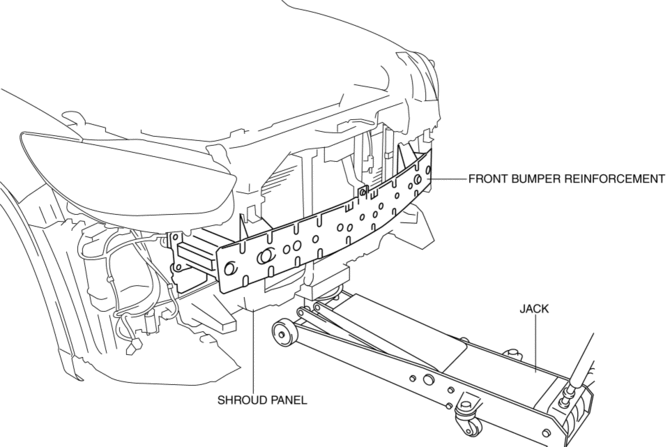
4. Remove the following parts:
a. Front bumper reinforcement.
b. Seal plate.
c. Hood latch.
d. Crash zone sensor.
e. Ambient temperature sensor.
f. Horn.
g. Air cleaner cover.
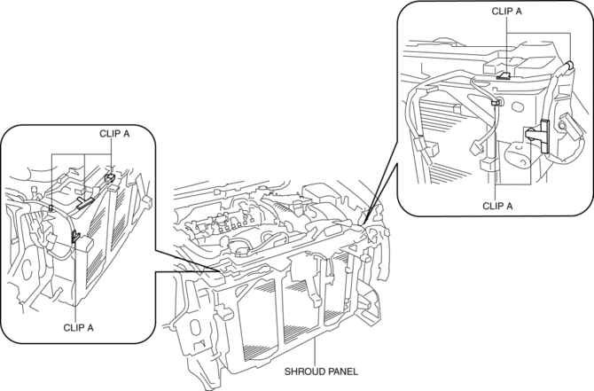
5. Remove clips A.
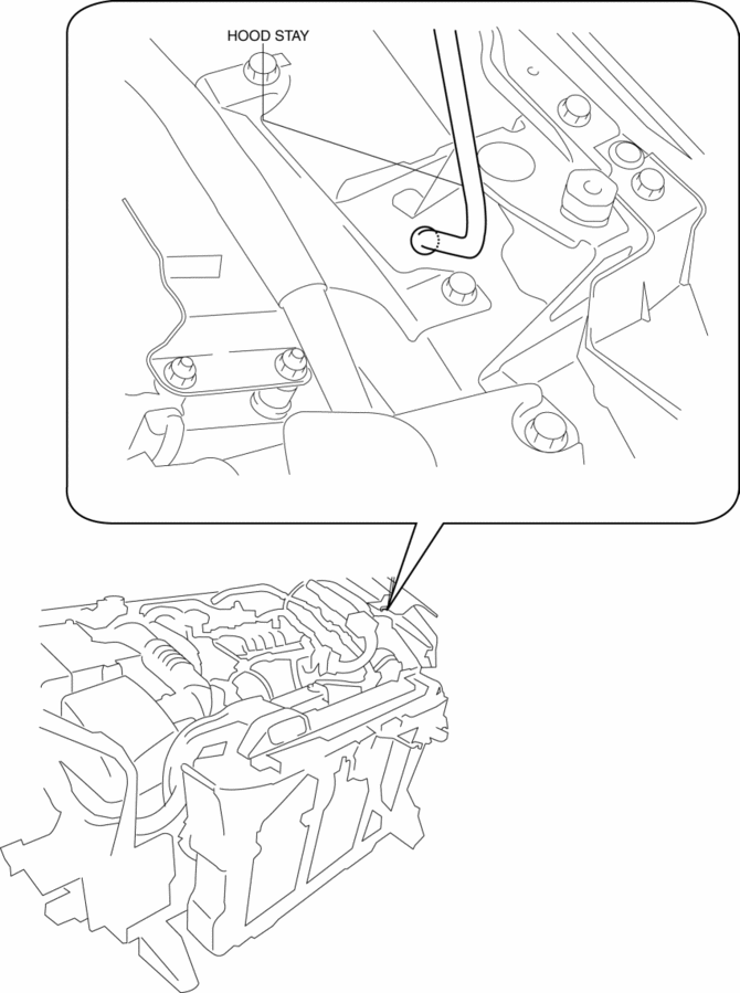
6. Remove the hood stay from the shroud panel, wrap the hood stay with protective tape, and install it as shown in the figure to support the hood.
7. Pull up the radiator in the direction of the arrow (1) shown in the figure.
CAUTION:
-
Removing the shroud panel without supporting it could cause the shroud panel to fall and cause serious injury. Always perform the procedure with at least another person to prevent the shroud panel from falling.
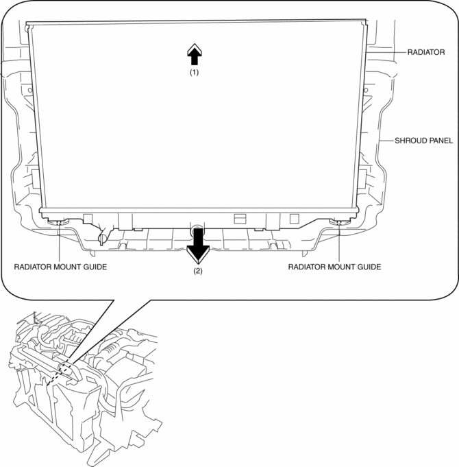
8. Pull down the shroud panel in the direction of the arrow (2) shown in the figure, then remove it from the radiator mount guide.
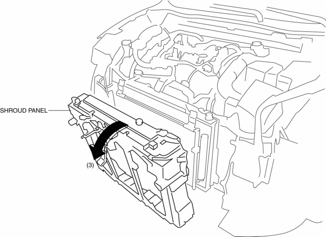
9. Remove the shroud panel in the direction of the arrow (3) shown in the figure.
CAUTION:
-
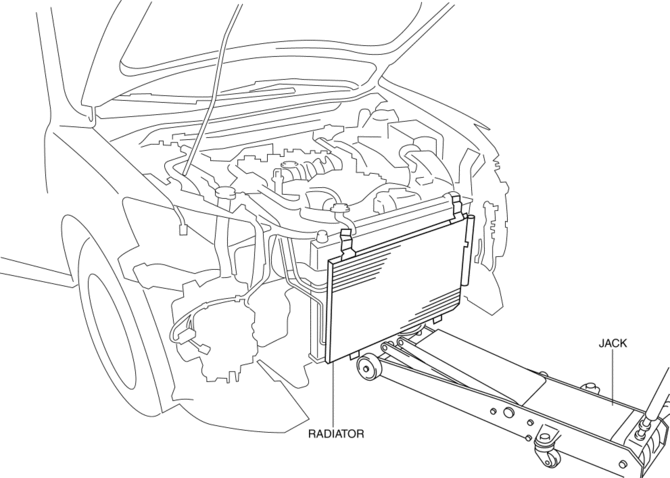
Support the lower surface of the radiator with a jack to prevent the radiator from falling off after the shroud panel is removed.
10. Install in the reverse order of removal.
11. Perform the headlight aiming procedure..
 Radiator
Purpose, Function
The radiator disperses the engine coolant heat flowing internally by receiving
against the vehicle while it is driven or air flow produced by the cooling fan.
Constru ...
 Shroud Side Member Installation [Panel Replacement]
Symbol Mark
Installation Procedure
1. When installing new parts, measure and adjust the body as necessary to conform
with standard dimensions.
2. Drill holes for the plug welding before inst ...
Other materials:
Audio Unit (Without Color LCD)
NOTE:
“iPod” is a registered trademark of Apple Inc. in the United States and other
countries.
Outline
The audio unit controls the CD, radio, exterior input devices (AUX/USB/iPod)
and the display.
Function
The display integrated into the audio unit display ...
Sirius Satellite Radio Unit Removal/Installation
CAUTION:
The audio unit communicates with the SIRIUS satellite radio unit and records
the presence/non-presence of the SIRIUS satellite radio unit when the ignition
is switched to ACC or ON (engine off or on) after connecting the negative battery
cable.
If the commander ...
Fuel Gauge Sender Unit Inspection [Awd]
Fuel gauge sender unit (main)
NOTE:
For the fuel gauge sender unit removal/installation, refer to the fuel pump
removal/installation because the fuel gauge sender unit is integrated with the
fuel pump..
1. Verify that the resistance at fuel gauge sender unit (main) terminals D a ...
