Mazda CX-5 Service & Repair Manual: Refrigerant Pressure Sensor Inspection [Manual Air Conditioner]
1. Install the manifold gauge.
2. Verify the high-pressure side reading of the manifold gauge.
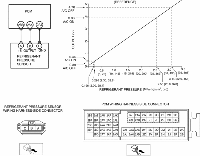
3. Measure the terminal voltage at PCM terminals 2BB, 2AX and 2AJ
4. Using the graph below, measure and verify the terminal voltage at 2AX.
5. Follow the PCM inspection when measuring the other terminal voltages..
-
Terminal 2BB: Approx. 5 V (Ignition switch on)
-
Terminal 2AJ: 1.0 V or less
-
If the each voltage is not normal, inspect the related wiring harness.
-
If there is any malfunction, replace the related wiring harness.
-
If wiring harness is normal, replace the refrigerant pressure sensor.

 Refrigerant Pressure Sensor Inspection [Full Auto Air Conditioner]
1. Install the manifold gauge.
2. Verify the high-pressure side reading of the manifold gauge.
3. Measure the terminal voltage at PCM terminal 2BB, 2AX and 2AJ
4. Using the graph below, measure ...
 Refrigerant Pressure Sensor Removal/Installation [Full Auto Air Conditioner]
1. Disconnect the negative battery cable..
2. Discharge the refrigerant..
3. Disconnect the refrigerant pressure sensor connector.
CAUTION:
If moisture or foreign material enters the ref ...
Other materials:
Ignition Coil [Skyactiv G 2.0]
Purpose, Function
The ignition coil generates high voltage by electromagnetic induction to
discharge the spark plug.
Construction
The ignition coil is installed to the upper part of the spark plug (direct
ignition coil).
With the adoption of the direct ignitio ...
Up Switch [Fw6 A EL, Fw6 Ax EL]
Purpose/Function
The up switch detects the shift up operation of the selector lever.
The up switch signal is sent to the TCM via CAN and is used for manual shift
control and engine-transaxle integration control.
Construction
The up switch is installed to the selector l ...
Lift Motor Removal/Installation
WARNING:
Handling a side air bag improperly can accidentally operate (deploy) the
air bag, which may seriously injure you. Read the service warnings/cautions
in the Workshop Manual before handling the front seat (side air bag integrated)..
1. Switch the ignition off (LOCK).
2. ...
