Mazda CX-5 Service & Repair Manual: Quick Release (Fuel System) Connector
Purpose, Function
-
Serviceability has been improved by the easy disconnection/connection.
Construction
-
The following types of the quick release connectors are used.
U.S.A. and CANADA
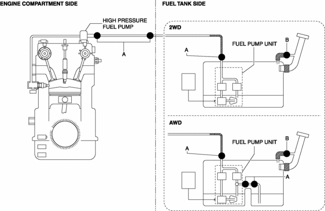
Except U.S.A. and CANADA
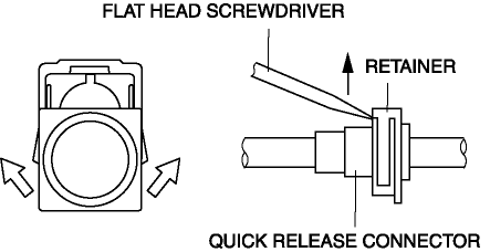
Type A
-
An SST is not used with this type.
-
Mainly consists of a retainer and O-ring. The quick release connector is integrated with the fuel hose and therefore cannot be disassembled.
-
When the quick release connector is connected, the fuel pipe projection is locked at the clamp lock point. To release the quick connector lock for each type, follow the procedure in the order shown in each figure.
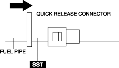
Type B
-
An SST is used with this type.
-
Consists of a retainer and O-ring. The quick release connector is integrated with the fuel hose and therefore cannot be disassembled.
-
To connect the quick release connector properly, push it into the fuel pipe until a click sound is heard.
-
New quick release connectors are fitted with a checker tab that prevent improper installation. This checker tab cannot normally be removed. When the quick release connector is properly connected to the fuel pipe, the lock is released and the checker tab comes off. Due to this, it can be verified that the quick release connector is completely connected.
 No.28 Fuel Filling Shut Off Concerns
28
FUEL FILLING SHUT OFF CONCERNS
DESCRIPTION
Fuel does not shut off properly.
POSSIBLE CAUSE
...
 Quick Release Connector Removal/Installation
WARNING:
Fuel is very flammable liquid. If fuel spills or leaks from the pressurized
fuel system, it will cause serious injury or death and facility breakage. Fuel
can also irritate skin ...
Other materials:
License Plate Light Bulb Removal/Installation
1. Disconnect the negative battery cable..
2. Insert a tape-wrapped flathead screwdriver into the clearance between the
lens and license plate light shown in the figure.
3. Move the flathead screwdriver in the direction of the arrow shown in the figure,
pull out the lens from the license ...
Bumper Bracket Removal [Panel Replacement]
Symbol Mark
Removal Procedure
1. Rough cut area locations indicated by (A).
2. Grind the 6 locations indicated by (B) shown in the figure.
CAUTION:
When grinding 6 locations indicated by (B) shown in the figure and the front
side frame is damaged, there is a possibility that ...
Master Cylinder
Purpose/Function
With the adoption of the master cylinder having an enlarged diameter (20.64
mm {0.8126 in}), brake pedal operability has been improved.
For vehicles with DSC, the diameter of the pipe between the master cylinder
and the DSC HU/CM has been increased, improving re ...
