Mazda CX-5 Service & Repair Manual: Plug Hole Plate Removal/Installation
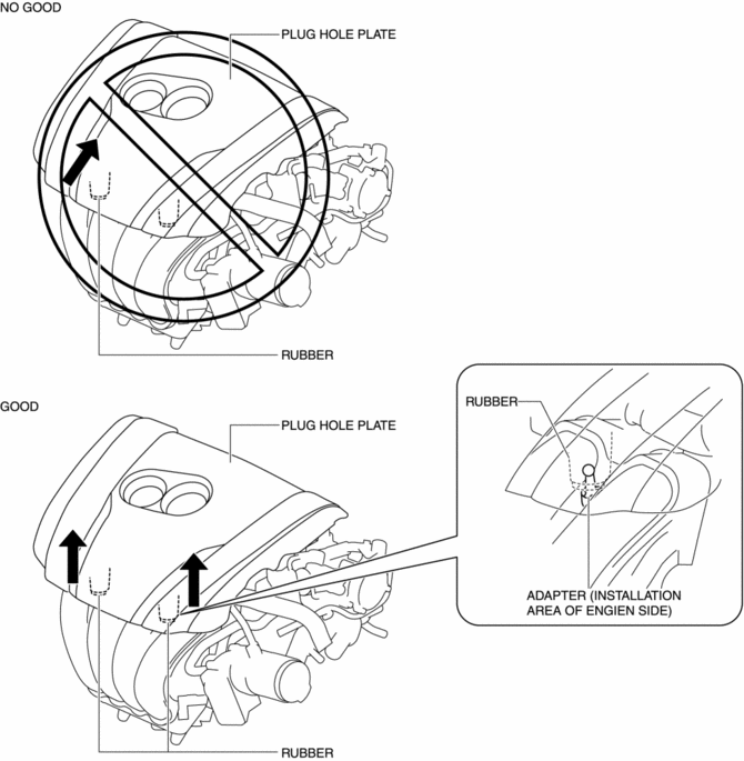
CAUTION:
-
If the rubber on only one side of the plug hole plate front is lifted up, it could damage the adapter at the location shown in the figure. When removing the plug hole plate, lift up the rubbers at the same time.
Removal
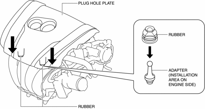
1. Pull up the front part of the plug hole plate at the same time and remove the rubber from the adapter on the engine side.

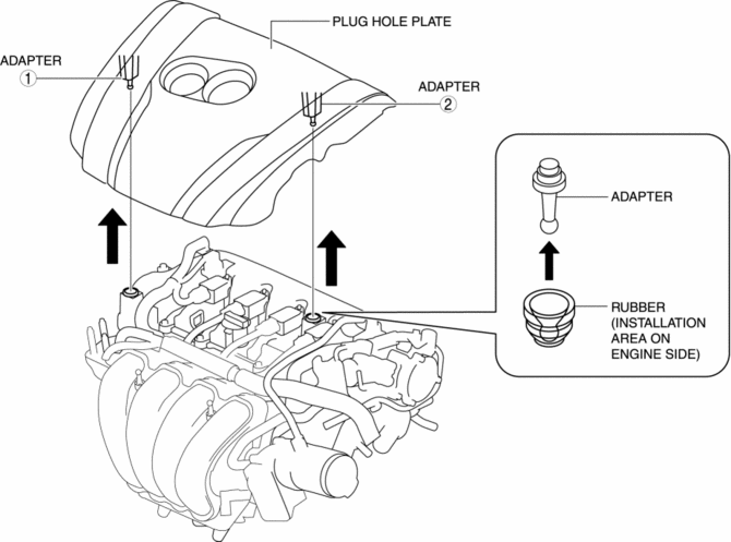
2. Pull up the plug hole plate in the order shown in the figure and remove the adapter from the rubber on the engine side.
Installation
1. Press the plug hole plate in the order shown in the figure to insert the adapter to the rubber on the engine side.

2. Press the front part of the plug hole plate at the same time to insert the rubber to the adapter on the engine side.
 Non Return Valve
Purpose, Function
Assures safety by preventing fuel from returning to the fuel filler opening.
Construction
The non-return valve cannot be removed as it is installed inside the fue ...
 Resonance Chamber
Purpose, Function
Pulsation of intake air is controlled and intake air noise is reduced by
adding an intake air passage.
Construction
The resonance chamber is installed to fresh ...
Other materials:
Fuel Gauge Sender Unit Inspection [Awd]
Fuel gauge sender unit (main)
NOTE:
For the fuel gauge sender unit removal/installation, refer to the fuel pump
removal/installation because the fuel gauge sender unit is integrated with the
fuel pump..
1. Verify that the resistance at fuel gauge sender unit (main) terminals D a ...
Washer Fluid Level Sensor Inspection
1. Disconnect the negative battery cable..
2. Set the front over fender aside..
3. Set the mudguard (RH) aside..
4. Remove the front bumper..
5. Inspect for continuity according to washer fluid level between the washer
fluid-level sensor terminals.
If not as indicated in th ...
Air Bag Module And Pre Tensioner Seat Belt Disposal Procedures [Standard Deployment
Control System]
WARNING:
A live (undeployed) air bag module or pre-tensioner seat belt may accidentally
operate (deploy) when it is disposed of and cause serious injury. Always refer
to the “AIR BAG MODULE AND PRE-TENSIONER SEAT BELT DEPLOYMENT PROCEDURES” and
dispose of air bag modules and pre ...
