
Mazda CX-5 Service & Repair Manual: Power Outer Mirror
Outline
-
The power outer mirror adjusts the outer mirror glass position up/down and left/right using the up/down adjustment motor and, left/right adjustment motor.
-
The up/down adjustment motor and, left/right adjustment motor turns clockwise (down/right direction) or counterclockwise (up/left direction).
Function
Up/down adjustment
-
When the up/down adjustment motor operates, the power outer mirror operates in the up/down directions.
Left/right adjustment
-
When the left/right adjustment motor operates, the power outer mirror operates in the left/right directions.
Construction
-
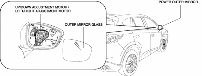
The up/down adjustment motor and left/right adjustment motor are equipped in the power outer mirror.
Operation
Up/down adjustment motor (Example: power outer mirror is operated upward)
1. The up/down adjustment motor receives an up signal from the power outer mirror switch, and when the up switch is turned on, it rotates counterclockwise.
Left/right adjustment motor (Example: power outer mirror is operated in left direction)
1. The left/right adjustment motor receives a left signal from the power outer mirror switch, and when the left switch is turned on, it rotates counterclockwise.
Fail-safe
-
Function not equipped
 Outer Mirror Glass Removal
1. Disconnect the negative battery cable..
2. Press area A of the outer mirror glass shown in the figure so that area B
moves outward.
3. Put your hand on the lower part of the outer mirror ...
 Power Outer Mirror Inspection
Mirror Glass Adjustment
1. Disconnect the negative battery cable..
2. Remove the following parts:
a. Inner garnish.
b. Front door trim.
c. Power outer mirror.
3. Apply battery positive volt ...
Other materials:
Relay And Fuse Block Removal/Installation
1. Remove the battery tray..
2. Remove the air cleaner case..
3. While pressing the relay and fuse block upper cover tab in the direction of
the arrow (1) shown in the figure, lift up the relay and fuse block upper cover
in the direction of the arrow (2) to detach the relay and fuse block up ...
Clock Spring Inspection [Two Step Deployment Control System]
1. Disconnect the negative battery cable and wait for 1 min or more..
2. Remove the driver?side air bag module..
3. Remove the steering wheel..
4. Remove the column cover..
5. Remove the clock spring..
6. Verify that the continuity is as indicated in the table.
If not as indicated ...
Charging System Warning Light [Skyactiv G 2.0]
Purpose, Function
Warns the driver of a charging system malfunction.
Construction
The charging system warning light is built into the instrument cluster..
Operation
Illuminates when a malfunction occurs in the charging system and DTCs is
stored in the PCM.
...
