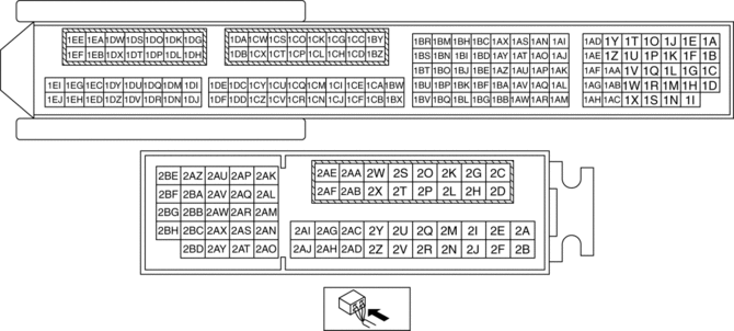
Mazda CX-5 Service & Repair Manual: PCM Inspection
Without Using the M-MDS
NOTE:
-
Because the PCM uses a waterproof connector, the inspection for the voltage/wave pattern cannot be performed. The following values are for reference.
Terminal voltage table (Reference)
|
Terminal |
Signal |
Connected to |
Test condition |
Voltage (V) |
inspection item |
|
|
1A*1 |
CAN_2H |
CAN system related modules |
Because this terminal is for CAN, good/no good judgment by terminal voltage is not possible. |
|
||
|
1B*1 |
CAN_2L |
CAN system related modules |
Because this terminal is for CAN, good/no good judgment by terminal voltage is not possible. |
|
||
|
1C |
— |
— |
— |
— |
— |
|
|
1D |
Knocking (–) |
KS |
Switch the ignition to ON (Use digital type voltmeter, because measurement voltage will be detected less than true voltage when using analog type voltmeter) |
Approx. 1.65 |
|
|
|
1E |
— |
— |
— |
— |
— |
|
|
1F |
— |
— |
— |
— |
— |
|
|
1G |
— |
— |
— |
— |
— |
|
|
1H |
Knocking (+) |
KS |
Switch the ignition to ON (Use digital type voltmeter, because measurement voltage will be detected less than true voltage when using analog type voltmeter) |
Approx. 3.38 |
|
|
|
1I |
GND |
Sensor shield |
Under any condition |
Below 1.0 |
|
|
|
1J |
Electric variable valve timing motor (rotation direction) |
Electric variable valve timing motor |
(See Electric variable valve timing motor (rotation direction) signal.) |
|
||
|
1K*2 |
Neutral position |
Neutral switch |
Shift lever is at neutral position |
Below 1.0 |
|
|
|
Shift lever is not at neutral position |
B+ |
|||||
|
1L*2 |
Back up light |
Back up light switch |
Shift lever is at R position |
Below 1.0 |
|
|
|
Shift lever is not at R position |
B+ |
|||||
|
1M |
— |
— |
— |
— |
— |
|
|
1N |
— |
— |
— |
— |
— |
|
|
1O |
Electric variable valve timing motor (rotation pulse) |
Electric variable valve timing motor |
(See Electric variable valve timing motor (rotation pulse) signal.) |
|
||
|
1P |
Oil pressure |
Oil pressure switch |
Switch the ignition to ON |
Below 1.0 |
|
|
|
Idle (after warm up) |
B+ |
|||||
|
1Q |
— |
— |
— |
— |
— |
|
|
1R |
— |
— |
— |
— |
— |
|
|
1S |
— |
— |
— |
— |
— |
|
|
1T |
Exhaust CMP |
Exhaust CMP sensor |
(See Exhaust CMP signal.) |
|
||
|
1U |
— |
— |
— |
— |
— |
|
|
1V |
— |
— |
— |
— |
— |
|
|
1W |
A/F |
A/F sensor |
Idle (after warm up) |
Approx. 4.2 |
|
|
|
1X |
GND |
Exhaust CMP sensor |
Under any condition |
Below 1.0 |
|
|
|
1Y |
Intake CMP |
Intake CMP sensor |
(See Intake CMP signal.) |
|
||
|
1Z |
— |
— |
— |
— |
— |
|
|
1AA |
— |
— |
— |
— |
— |
|
|
1AB |
A/F |
A/F sensor |
Idle (after warm up): 0 mA |
|
||
|
1AC |
GND |
Intake CMP sensor |
Under any condition |
Below 1.0 |
|
|
|
1AD |
CKP |
CKP sensor |
(See CKP signal.) |
|
||
|
1AE |
Electric variable valve timing driver (diagnostic) |
Electric variable valve timing driver |
(See Electric variable valve timing driver (diagnostic) signal.) |
|
||
|
1AF |
Generator output voltage |
Generator (terminal P) |
(See Generator output voltage.) |
|
||
|
1AG |
A/F |
A/F sensor |
Idle (after warm up) |
Approx. 3.48 |
|
|
|
1AH |
GND |
CKP sensor |
Under any condition |
Below 1.0 |
|
|
|
1AI |
Purge control |
Purge solenoid valve |
(See Purge control.) |
|
||
|
1AJ |
IGT4 |
Ignition coil No.4 |
(See IGT1, IGT2, IGT3, IGT4 control.) |
|
||
|
1AK |
ECT (No.1) |
ECT sensor No.1 |
Switch the ignition to ON |
ECT 20 °C {68 °F} |
Approx. 3.10 |
|
|
ECT 40 °C {104 °F} |
Approx. 2.16 |
|||||
|
ECT 60 °C {140 °F} |
Approx. 1.40 |
|||||
|
ECT 80 °C {176 °F} |
Approx. 0.87 |
|||||
|
ECT 100 °C {212 °F} |
Approx. 0.54 |
|||||
|
1AL |
— |
— |
— |
— |
— |
|
|
1AM |
GND |
ECT sensor No.1 |
Under any condition |
Below 1.0 |
|
|
|
1AN |
Hydraulic variable valve timing control |
OCV |
(See Hydraulic variable valve timing control signal.) |
|
||
|
1AO |
IGT3 |
Ignition coil No.3 |
(See IGT1, IGT2, IGT3, IGT4 control.) |
|
||
|
1AP |
— |
— |
— |
— |
— |
|
|
1AQ |
— |
— |
— |
— |
— |
|
|
1AR |
— |
— |
— |
— |
— |
|
|
1AS |
Engine oil control |
Engine oil solenoid valve |
(See Engine oil control signal.) |
|
||
|
1AT |
IGT2 |
Ignition coil No.2 |
(See IGT1, IGT2, IGT3, IGT4 control.) |
|
||
|
1AU |
— |
— |
— |
— |
— |
|
|
1AV |
Ion (No.4) |
Ion sensor No.4 |
Idle (after warm up) |
Approx. 4.55 |
|
|
|
1AW |
— |
— |
— |
— |
— |
|
|
1AX |
— |
— |
— |
— |
— |
|
|
1AY |
IGT1 |
Ignition coil No.1 |
(See IGT1, IGT2, IGT3, IGT4 control.) |
|
||
|
1AZ |
Electric variable valve timing control |
Electric variable valve timing driver |
(See Electric variable valve timing control signal.) |
|
||
|
1BA |
Ion (No.3) |
Ion sensor No.3 |
Idle (after warm up) |
Approx. 4.55 |
|
|
|
1BB |
GND |
Sensor shield |
Under any condition |
Below 1.0 |
|
|
|
1BC |
— |
— |
— |
— |
— |
|
|
1BD |
— |
— |
— |
— |
— |
|
|
1BE |
Generator field coil control |
Generator (terminal D) |
(See Generator field coil control signal.) |
|
||
|
1BF |
Ion (No.2) |
Ion sensor No.2 |
Idle (after warm up) |
Approx. 4.55 |
|
|
|
1BG |
GND |
Sensor shield |
Under any condition |
Below 1.0 |
|
|
|
1BH |
— |
— |
— |
— |
— |
|
|
1BI |
— |
— |
— |
— |
— |
|
|
1BJ |
Constant voltage (Vref) |
Fuel pressure sensor |
Switch the ignition to ON |
Approx. 5.0 |
|
|
|
1BK |
Ion (No.1) |
Ion sensor No.1 |
Idle (after warm up) |
Approx. 4.55 |
|
|
|
1BL |
GND |
Sensor shield |
Under any condition |
Below 1.0 |
|
|
|
1BM |
— |
— |
— |
— |
— |
|
|
1BN |
Constant voltage (Vref) |
CKP sensor |
Switch the ignition to ON |
Approx. 5.0 |
|
|
|
1BO |
Constant voltage (Vref) |
MAP sensor |
Switch the ignition to ON |
Approx. 5.0 |
|
|
|
1BP |
TP (No.1) |
TP sensor No.1 |
Switch the ignition to ON |
Accelerator pedal released |
Approx. 1.11 |
|
|
Accelerator pedal depressed |
Approx. 4.59 |
|||||
|
1BQ |
GND |
TP sensor No.1, TP sensor No.2 |
Under any condition |
Below 1.0 |
|
|
|
1BR |
— |
— |
— |
— |
— |
|
|
1BS |
Constant voltage (Vref) |
TP sensor No.1, TP sensor No.2 |
Switch the ignition to ON |
Approx. 5.0 |
|
|
|
1BT |
— |
— |
— |
— |
— |
|
|
1BU |
TP (No.2) |
TP sensor No.2 |
Switch the ignition to ON |
Accelerator pedal released |
Approx. 3.92 |
|
|
Accelerator pedal depressed |
Approx. 0.41 |
|||||
|
1BV |
— |
— |
— |
— |
— |
|
|
1BW |
MAP |
MAP sensor |
Switch the ignition to ON |
Approx. 4.07 |
|
|
|
Idle (after warm up) |
Approx. 1.34 |
|||||
|
Racing (Engine speed: 2,000 rpm) |
Approx. 1.05 |
|||||
|
1BX |
GND |
MAP sensor, IAT sensor No.2 |
Under any condition |
Below 1.0 |
|
|
|
1BY |
A/F sensor heater control |
A/F sensor heater |
(See A/F sensor heater control signal.) |
|
||
|
1BZ |
GND |
GND |
Under any condition |
Below 1.0 |
|
|
|
1CA |
Fuel pressure |
Fuel pressure sensor |
Switch the ignition to ON |
Approx. 1.22 |
|
|
|
Idle (after warm up) |
Approx. 1.06 |
|||||
|
1CB |
GND |
Fuel pressure sensor |
Under any condition |
Below 1.0 |
|
|
|
1CC |
Drive-by-wire control (–) |
Throttle valve actuator |
Switch the ignition to ON |
Approx. 10.51 |
|
|
|
Idle (after warm up) |
B+ |
|||||
|
1CD |
— |
— |
— |
— |
— |
|
|
1CE |
IAT (No.2) |
IAT sensor No.2 |
Switch the ignition to ON |
IAT 20 °C {68 °F} |
Approx. 3.57 |
|
|
IAT 40 °C {104 °F} |
Approx. 2.70 |
|||||
|
IAT 60 °C {140 °F} |
Approx. 1.87 |
|||||
|
1CF |
— |
— |
— |
— |
— |
|
|
1CG |
Drive-by-wire control (+) |
Throttle valve actuator |
(See Drive-by-wire control (+) signal.) |
|
||
|
1CH |
— |
— |
— |
— |
— |
|
|
1CI |
— |
— |
— |
— |
— |
|
|
1CJ |
— |
— |
— |
— |
— |
|
|
1CK |
Battery voltage |
Main relay |
Switch the ignition to ON |
B+ |
|
|
|
1CL |
GND |
GND |
Under any condition |
Below 1.0 |
|
|
NOTE:
When performing configuration, it is necessary to read the vehicle specification
information from the PCM before replacing it. Connect the M-MDS to the vehicle
and perform vehicle ...
| ||||||


