Mazda CX-5 Service & Repair Manual: Oil Control Valve (OCV) Inspection
Coil Resistance Inspection
1. Disconnect the negative battery cable..
2. Remove the plug hole plate..
3. Disconnect the OCV connector.
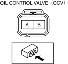
4. Measure the resistance between terminals A and B using an ohmmeter.

-
OCV coil resistance
-
6.9—7.5 ohms [20°C {68°F}]
-
If not as specified, replace the OCV..
5. Install in the reverse order of removal.
Spool Valve Operation Inspection
1. Disconnect the negative battery cable..
2. Remove the OCV..
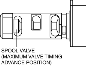
3. Verify that the spool valve in the OCV is in the maximum valve timing advance position as indicated in the figure.

-
If not as specified, replace the OCV..
4. Verify that the battery is fully charged..
-
If not as specified, recharge the battery..
NOTE:
-
When applying battery positive voltage between the OCV terminals, the connection can be either of the following:
-
Positive battery cable to terminal A, negative battery cable to terminal B
-
Positive battery cable to terminal B, negative battery cable to terminal A

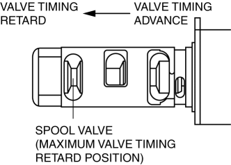
5. Apply battery positive voltage between the OCV terminals and verify that the spool valve operates and moves to the maximum valve timing retard position.

-
If not as specified, replace the OCV..
6. Stop applying battery positive voltage and verify that the spool valve returns to the maximum valve timing advance position.
-
If not as specified, replace the OCV..
7. Install the OCV..
 Lubrication System
Outline
Pressure loss is reduced by optimizing the oil passage.
With the adoption of the chain drive type oil pump, oil pump drive force
has been reduced.
With the adoption o ...
 Oil Control Valve (OCV) Removal/Installation
WARNING:
A hot engine can cause severe burns. Turn off the engine and wait until it
is cool before servicing.
1. Disconnect the negative battery cable..
2. Remove the plug hole plat ...
Other materials:
Rear Seat Back Trim Removal/Installation
6:4 Split Type
1. Remove the trunk board..
2. Remove the rear seat back..
3. Remove the headrest.
4. Remove the rear seat back frame..
5. Remove the C rings in the order of (1), (2), (3), and (4) shown in the figure,
and remove the rear seat back trim from the rear seat back pad.
CA ...
Cooling System Cap Inspection
WARNING:
Never remove the cooling system cap or loosen the radiator drain plug while
the engine is running, or when the engine and radiator are hot. Scalding engine
coolant and steam may shoot out and cause serious injury. It may also damage
the engine and cooling system.
Tu ...
Clutch Pedal Inspection [C66 M R]
NOTE:
For the clutch pedal inspection, note the following and measure each inspection
location.
Measure the center of the upper surface of the pedal pad for each inspection.
If the distance from the pedal pad to the floor covering is measured,
measure the short ...
