Mazda CX-5 Service & Repair Manual: Odometer/Tripmeter
Purpose
-
The odometer/tripmeter notifies the user of the total travel distance or the traveled distance over a specific interval.
Function
-
The instrument cluster calculates the traveled distance based on the traveled distance signal from the PCM and displays it.
-
The instrument cluster stores the calculated travel distance in the microcomputer of the instrument cluster.
Odometer calculation function
-
The instrument cluster calculates the total traveled distance based on the traveled distance signal from the PCM and the stored traveled distance, and displays it.
-
The total traveled distance which can be displayed is from 0 to 999,999.
Tripmeter A/B calculation function
-
The instrument cluster calculates the traveled distance based on the traveled distance signal from the PCM and the traveled distance from when the tripmeter is reset, and displays it.
-
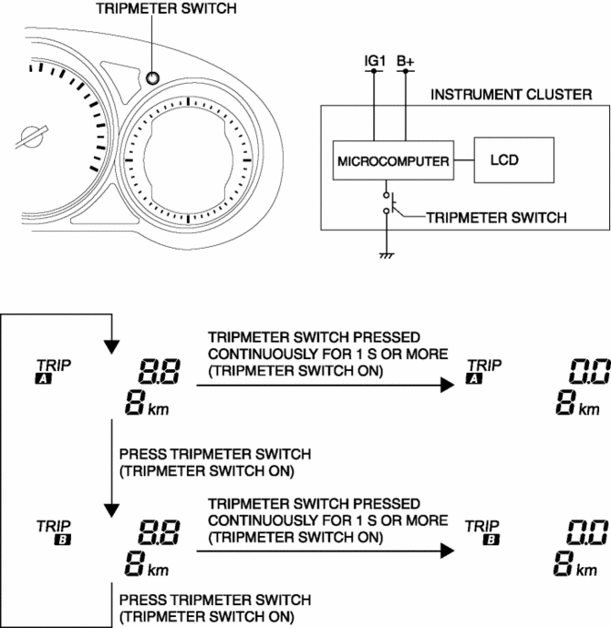
There are A and B tripmeters and the display for each can be switched with each press of the tripmeter switch.
-
If the tripmeter switch is continuously pressed for approx. 1 s or more
, the tripmeter traveled distance is reset (0.0)
-
The traveled distance which can be displayed is from 0.0 to 999.9. After 999.9, it returns to 0.
Construction
-
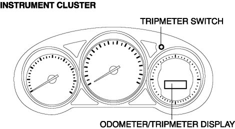
The odometer/tripmeter is displayed in the LCD of the instrument cluster.
-
The tripmeter switch is installed to the instrument cluster.
-
The calculation for the odometer/tripmeter display and the traveled distance is performed by the instrument cluster microcomputer.
Operation
-
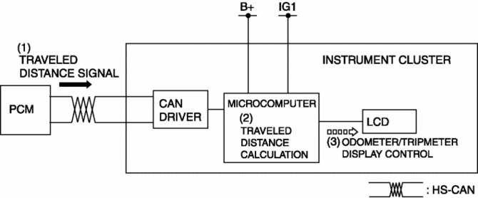
The instrument cluster receives (1) the traveled distance signal from the PCM when the ignition is switched ON (engine on).
-
The instrument cluster calculates the traveled distance (2) in the recorded total traveled distance (odometer) data and the traveled distance over a specific interval (tripmeter) based on the received traveled distance signal.
-
The instrument cluster displays (3) the calculated travel distance in the LCD.
Odometer/tripmeter switching operation
-
The instrument cluster switches the odometer/tripmeter display when a tripmeter switch ON is detected.
-
The instrument cluster returns the traveled distance display to 0.0 when a tripmeter switch ON is detected for 1 s or more while tripmeter A or B is displayed.
Fail-safe
-
Function not equipped.
 Fuel Gauge Sender Unit Removal/Installation [Awd]
WARNING:
Always keep sparks and flames away from fuel when servicing the fuel system.
Fuel can be easily ignited which could cause serious injury or death, and damage
to equipment.
...
 Speedometer
Purpose
The speedometer notifies the driver of the speed at which the vehicle is
traveling.
Function
The instrument cluster controls the speedometer needle based on the vehicle ...
Other materials:
Registering Your Vehicle in A Foreign Country (Except United States and Canada)
Registering your vehicle in a foreign country may be problematic depending on
whether it meets the specific emission and safety standards of the country in which
the vehicle will be driven. Consequently, your vehicle may require modifications
at personal expense in order to meet the regulation ...
Engine Mount
Purpose, Function
The engine mount secures the engine and transaxle to the vehicle body, reducing
vibration and noise.
Construction
The three points at the engine front (No.3 engine mount), one side of the
transaxle (No.1 engine mount), and the rear upper part of the transa ...
Front Pillar Installation [Panel Replacement]
Symbol Mark
Installation Procedure
1. When installing new parts, measure and adjust the body as necessary to conform
with standard dimensions.
2. Drill holes for the plug welding before installing the new parts.
3. After temporarily installing new parts, make sure the related parts fit p ...
