
Mazda CX-5 Service & Repair Manual: Inner Garnish Removal/Installation
1. Take the shaded area shown in the figure, and pull the inner garnish in the direction of the arrow (1) while detaching clips A.
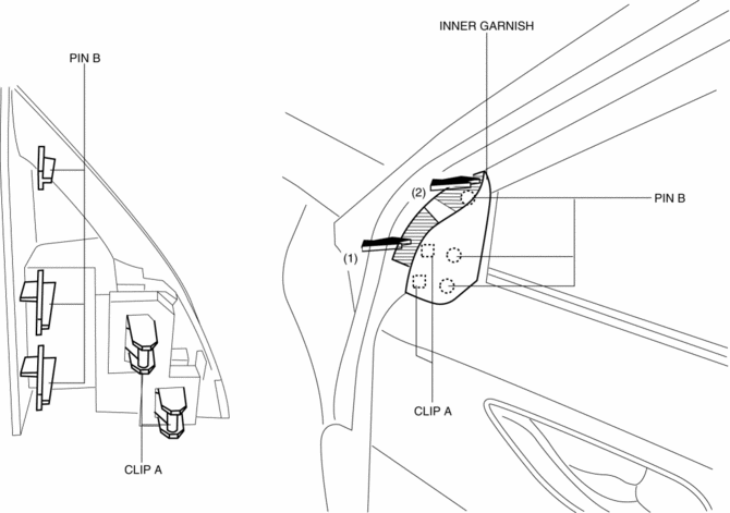
2. Take the shaded area shown in the figure, and remove the inner garnish in the direction of the arrow (2) while detaching pins B.
3. Install in the reverse order of removal.
 Headliner Removal/Installation
1. Disconnect the negative battery cable..
2. Remove the following parts:
a. Sunroof seaming welt (with sunroof system).
b. A-pillar trim.
c. Front map light.
d. Sunvisor.
e. Front scuff p ...
 Interior Trim
Outline
A headliner equipped with a shock absorbing pad has been adopted.
The front and rear door trims are also equipped with shock absorbing pads.
Construction
...
Other materials:
Air Bag System Warning Alarm [Two Step Deployment Control System]
Purpose
The air bag system warning alarm notifies the driver that a malfunction occurred
in the air bag system instead of the air bag system warning light.
Function
If a malfunction occurs in the air bag system while the air bag system warning
light cannot illuminate, the a ...
Constant Monitoring
The following components of the air bag systems are monitored by a diagnostic
system:
• Crash sensors, and diagnostic module (SAS
unit)
• Front air bag sensors
• Air bag modules
• Side crash sensors
• Air bag/Front seat belt pretensioner system
warning light
• Fron ...
High Mount Brake Light
Purpose
The high-mount brake light signals vehicles to the rear that the vehicle
is stopped.
Function
The high-mount brake light illuminates in conjunction with the operation
of the brake light switch.
Construction
The high-mount brake light is positioned on th ...
