Mazda CX-5 Service & Repair Manual: High Clutch [Fw6 A EL, Fw6 Ax EL]
Purpose/Function
-
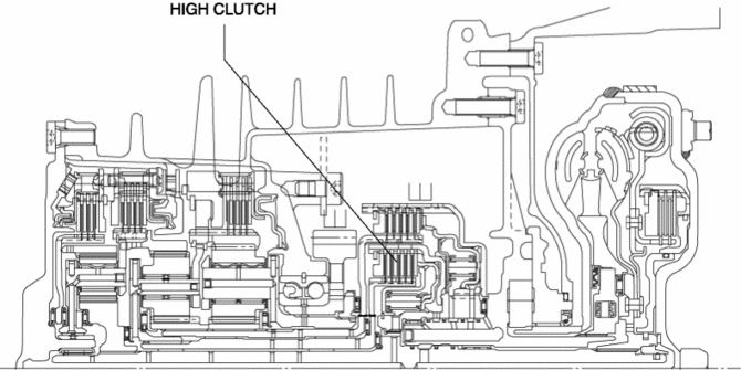
The high clutch operates in 4GR, 5GR, and 6GR and intermittently operates the rear carrier by drive force from the turbine shaft.
-
For the high clutch, a centrifugal balance clutch has been adopted to prevent clutch drag and to assure stabilized piston thrust in all engine speed ranges.
Construction
-
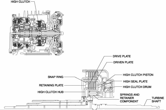
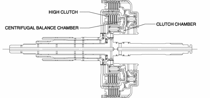
The high clutch consists of the following parts shown in the figure.
-
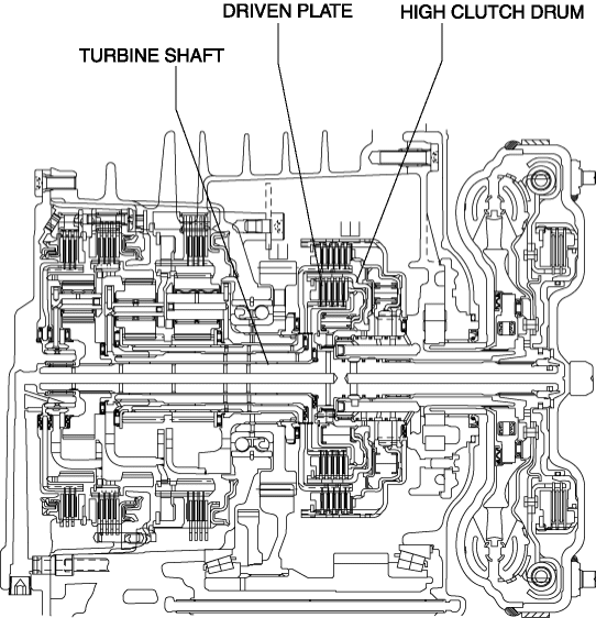
The driven plate of the high clutch is engaged with the high clutch drum. The high clutch drum is engaged with the turbine shaft and spline, and when the turbine shaft rotates, the high clutch drum and driven plate rotate as a single unit.
-
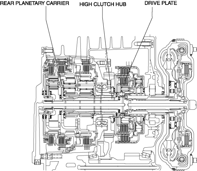
The drive plate of the high clutch is engaged with the high clutch hub. The high clutch hub is engaged with the rear carrier, and the drive plate, high clutch hub, and rear carrier rotate as a single unit.
-
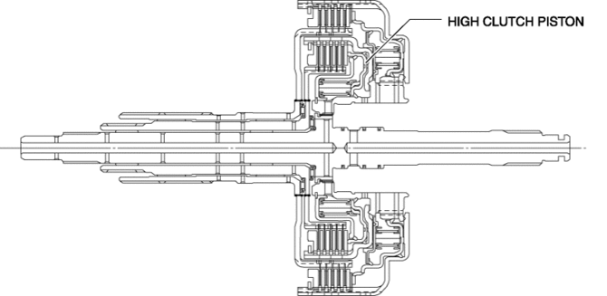
For the high clutch piston, a compact and highly reliable bonded seal piston has been adopted in which the piston and seal are molded together.
Centrifugal balance clutch
-
The centrifugal balance clutch is built into the high clutch.
-
The centrifugal balance chamber is positioned opposing the clutch chamber for the high clutch. In the centrifugal balance chamber, ATF is constantly charged through a specialized hydraulic circuit.
Operation
-
If hydraulic pressure is applied to the high clutch piston, the drive plate and driven plate are pressure coupled and drive force from the turbine shaft is transmitted to the rear planetary carrier. In addition, drive force is also transmitted to the front internal gear through the rear planetary gear.
Centrifugal balance clutch
-
Clutch pressure not applied
-
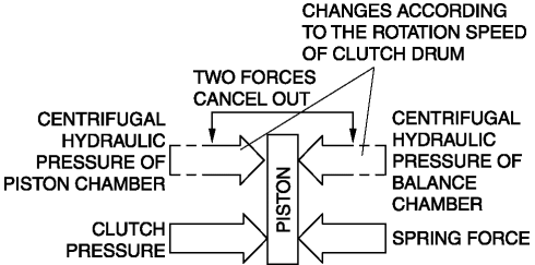
When the clutch drum rotates, centrifugal force is applied to the remaining ATF in the clutch chamber to push the piston, but centrifugal force is also applied to the ATF in the centrifugal balance chamber to force the piston to move back. As a result, the opposing forces of the clutch and balance chambers are offset and the piston does not move, preventing clutch drag.
-
Clutch pressure applied
-
When clutch pressure is applied to the clutch chamber, the piston, which overcomes the opposing centrifugal hydraulic pressure from the balance chamber and the spring force, is pushed in the direction of clutch engagement and the clutch is engaged. At this time, because the centrifugal hydraulic pressure applied to the clutch pressure in the clutch chamber is offset by the centrifugal hydraulic pressure applied to the balance chamber, the effect of piston thrust by the centrifugal force from the clutch drum rotation is eliminated. As a result, stabilized piston force in all engine speed ranges is assured, thus reducing shift shock.
 Front Seat Side Cover Removal/Installation
WARNING:
Handling a side air bag improperly can accidentally operate (deploy) the
air bag, which may seriously injure you. Read the service warnings in the Workshop
Manual before handlin ...
 Initial Learning [Fw6 A EL, Fw6 Ax EL]
Introduction
If the control valve body and oil pressure switch are replaced, always perform
the initial learning. If the initial learning is not completed, engine rev-up
may occur or shif ...
Other materials:
Active Command Modes Inspection [Instrument Cluster]
1. Connect the M-MDS to the DLC-2.
2. After the vehicle is identified, select the following items from the initialization
screen of the M-MDS.
a. Select “DataLogger”.
b. Select “Modules”.
c. Select “IC”.
3. Select the simulation items from the PID table.
4. Perform the acti ...
Heated Oxygen Sensor (HO2 S) Removal/Installation
WARNING:
A hot engine and exhaust system can cause severe burns. Turn off the engine
and wait until they are cool before removing the exhaust system.
CAUTION:
Do not allow flammable objects such as the taping for bundling wiring harness
to come into contact with the exhau ...
Rear Shock Absorber Disposal
WARNING:
Whenever drilling into a rear shock absorber, wear protective eye wear. The
gas in the rear shock absorber is pressurized, and could spray metal chips into
the eyes and face when drilling.
1. Clamp a rear shock absorber on a flat surface or with the piston pointing
...
