Mazda CX-5 Service & Repair Manual: Generator Control [Skyactiv G 2.0]
Outline
-
Idling stability has been improved by optimum control of generator voltage according to engine operation and electrical load conditions.
-
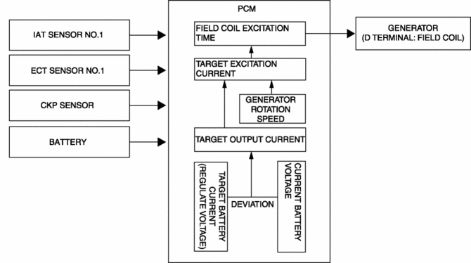
The PCM determines the engine operation and electrical load conditions based on the input signals from each control part and controls the energization time of the generator field coils.
Block Diagram

Operation
Determination method for target excitation current
-
The target excitation current is calculated from the generator target output amount (determined by intake air temperature, engine speed, and vehicle speed), and the actual generator rotation speed.
Determination method for field coil excitation time
-
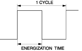
The PCM increases or decreases the field coil excitation current by sending a duty signal to the power transistor built into the generator.
-
The field coil energization current changes according to changes in the power transistor excitation time by changing the duty signal duty ratio. For example, when the battery positive voltage drops, the duty ratio of the duty signal sent to the power transistor is larger, increasing the field coil excitation current.

-
During deceleration fuel-cut, the PCM increases the generator voltage and stores electricity in the battery. At times other than deceleration, the PCM enables electric discharge from the battery to reduce the generator load.
-
Directly after the engine is started, the generator load is decreased by charging only to the necessary level according to the battery conditions in which the battery has not been charged to the maximum.
 Charging System [Skyactiv G 2.0]
Outline
Regulator-less generator (built-in power transistor) has been adopted.
A generator using two delta connection type stator coils has been adopted.
Structural View
Stru ...
 Generator Disassembly/Assembly [Skyactiv G 2.0]
CAUTION:
Melt the solder quickly, otherwise the diodes (rectifier) and regulator will
be damaged by excessive heat.
1. Disassemble in the order indicated in the table.
2. Assemble i ...
Other materials:
Rear Stabilizer Removal/Installation [Awd]
WARNING:
Verify that the rear crossmember is securely supported by a jack. If the
rear crossmember falls off, it can cause serious injury or death, and damage
to the vehicle.
CAUTION:
Performing the following procedures without first removing the rear ABS wheel-spee ...
Rear Crossmember Removal/Installation [2 Wd]
WARNING:
Verify that the rear crossmember is securely supported by a jack. If the
rear crossmember falls off, it can cause serious injury or death, and damage
to the vehicle.
CAUTION:
Performing the following procedures without first removing the rear ABS wheel-speed
s ...
Ignition Coil [Skyactiv G 2.0]
Purpose, Function
The ignition coil generates high voltage by electromagnetic induction to
discharge the spark plug.
Construction
The ignition coil is installed to the upper part of the spark plug (direct
ignition coil).
With the adoption of the direct ignitio ...
